Method for measuring and correcting multi-wire skew

a multi-wire skew and measurement method technology, applied in the field of communication system circuits, can solve problems such as thwarting decoding, and achieve the effect of improving the quality of received signals and reliably detecting data values transmitted over communications systems

Active Publication Date: 2020-06-16
KANDOU LABS
View PDF454 Cites 9 Cited by
  • Summary
  • Abstract
  • Description
  • Claims
  • Application Information

AI Technical Summary

Benefits of technology

[0018]To reliably detect the data values transmitted over a communications system, a receiver accurately measures the received signal value amplitudes at carefully selected times. For vector signaling codes communicated essentially in parallel, this timing selection is comprised of two parts: accurate sampling of individual codeword elements received on individual wires or communications channels, and accurate interpretation of the entire received codeword, regardless of timing variations in reception of its component elements.
[0019]These differential propagation times across the vector signaling code codeword may be caused by variations in transmission path length or propagation velocity, and may be constant or vary over time. Identifying and correcting such differential arrival times or “skew” will increase the timing window for proper reception, thus improving received signal quality. Accurately measuring skew at the receiver is essential to subsequent skew correction, which as one example may be performed by introducing variable delays into the individual wire or symbol data paths prior to codeword decoding.

Problems solved by technology

Where the group of signals is communicated essentially in parallel over multiple wires or communications channels, variations in propagation delay over the multiple wires or channels can cause elements comprising one group of signals or codeword to be received at different times. This “skew” may, if uncorrected, prevent codewords from being received as coherent entities, and thus thwart decoding.

Method used


Image

  • Method for measuring and correcting multi-wire skew
  • Method for measuring and correcting multi-wire skew
  • Method for measuring and correcting multi-wire skew

Examples


Embodiment Construction

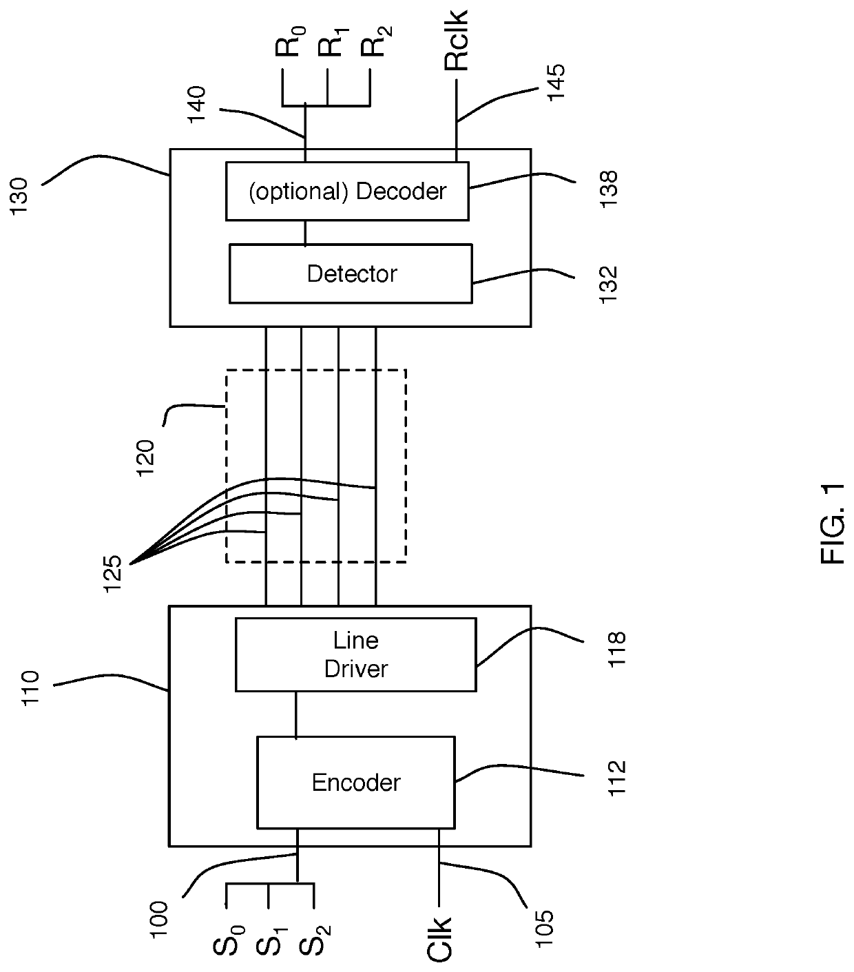
[0033]As described in [Cronie I], vector signaling codes may be used to produce extremely high bandwidth data communications links, such as between two integrated circuit devices in a system. Multiple data communications channels transmit symbols of the vector signaling code, acting together to communicate codewords of the vector signaling code. Depending on the particular vector signaling code used, the number of channels comprising a communications link may range from two to eight or more. Individual symbols, e.g. transmissions on any single communications channel, may utilize multiple signal levels, often three or more.

[0034]Embodiments may also apply to any communication or storage methods requiring coordination of multiple channels or elements of the channel to produce a coherent aggregate result.

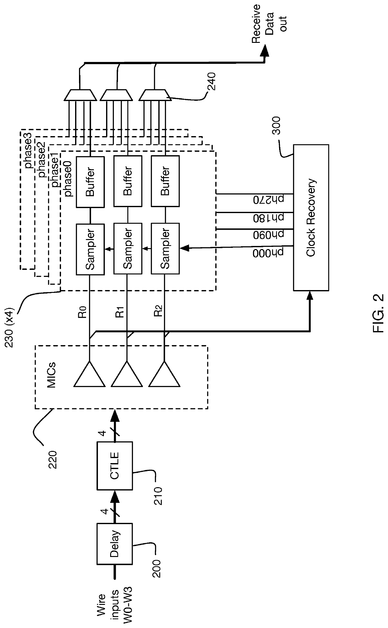
Input Sampling Circuits

[0035]Conventional practice for a high-speed integrated circuit receiver includes terminating each data line (after any relevant front end processing such as amp...


PUM


Abstract

Generating, during a first and second signaling interval, an aggregated data signal by forming a linear combination of wire signals received in parallel from wires of a multi-wire bus, wherein at least some of the wire signals undergo a signal level transition during the first and second signaling interval; measuring a signal skew characteristic of the aggregated data signal; and, generating wire-specific skew offset metrics, each wire-specific skew offset metric based on the signal skew characteristic.

Description

REFERENCES[0001]The following prior applications are herein incorporated by reference in their entirety for all purposes:[0002]U.S. Patent Publication 2011 / 0268225 of application Ser. No. 12 / 784,414, filed May 20, 2010, naming Harm Cronie and Amin Shokrollahi, entitled “Orthogonal Differential Vector Signaling” (hereinafter “Cronie I”).[0003]U.S. patent application Ser. No. 13 / 842,740, filed Mar. 15, 2013, naming Brian Holden, Amin Shokrollahi and Anant Singh, entitled “Methods and Systems for Skew Tolerance in and Advanced Detectors for Vector Signaling Codes for Chip-to-Chip Communication”, hereinafter identified as [Holden I];[0004]U.S. patent application Ser. No. 14 / 926,958, filed Oct. 29, 2015, naming Richard Simpson, Andrew Stewart, and Ali Hormati, entitled “Clock Data Alignment System for Vector Signaling Code Communications Link”, hereinafter identified as [Simpson I].[0005]U.S. patent application Ser. No. 14 / 717,717, filed May 20, 2015, naming Richard Simpson and Roger Ulr...

Claims


Application Information

Patent Timeline
Patent Type & Authority Patents(United States)
IPC IPC(8): H04L7/00H04L25/14H04L7/033H04L25/03H04L25/49
CPCH04L25/49H04L7/0054H04L25/03H04L7/0016H04L7/033H04L7/0079H04L25/4904H04L25/03057H04L25/14H04L2025/03356H04L7/0025H04L25/03878H04L25/03012H04L25/4919H04L25/0272
Inventor ULRICH, ROGERTAJALLI, ARMINHORMATI, ALISIMPSON, RICHARD
Owner KANDOU LABS
Why Eureka
Try Eureka