
Movable brace frame for self-installing platform

a self-installing, brace frame technology, applied in the direction of artificial islands, foundation engineering, construction, etc., can solve the problems of not being able to tow the platform on a barge, the platform cannot be installed in relative shallow water and/or benign environments, and the method is expensive, so as to reduce leg stress, prevent large overall platform sway, and increase the rigidity of legs

Inactive Publication Date: 2011-12-15
KEPPEL OFFSHORE & MARINE TECH CENT PTE LTD
View PDF19 Cites 28 Cited by
  • Summary
  • Abstract
  • Description
  • Claims
  • Application Information

AI Technical Summary

Benefits of technology

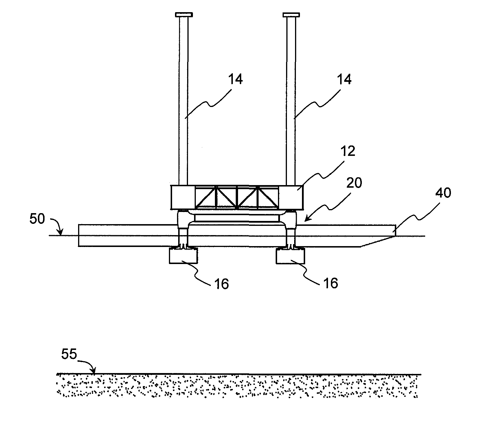
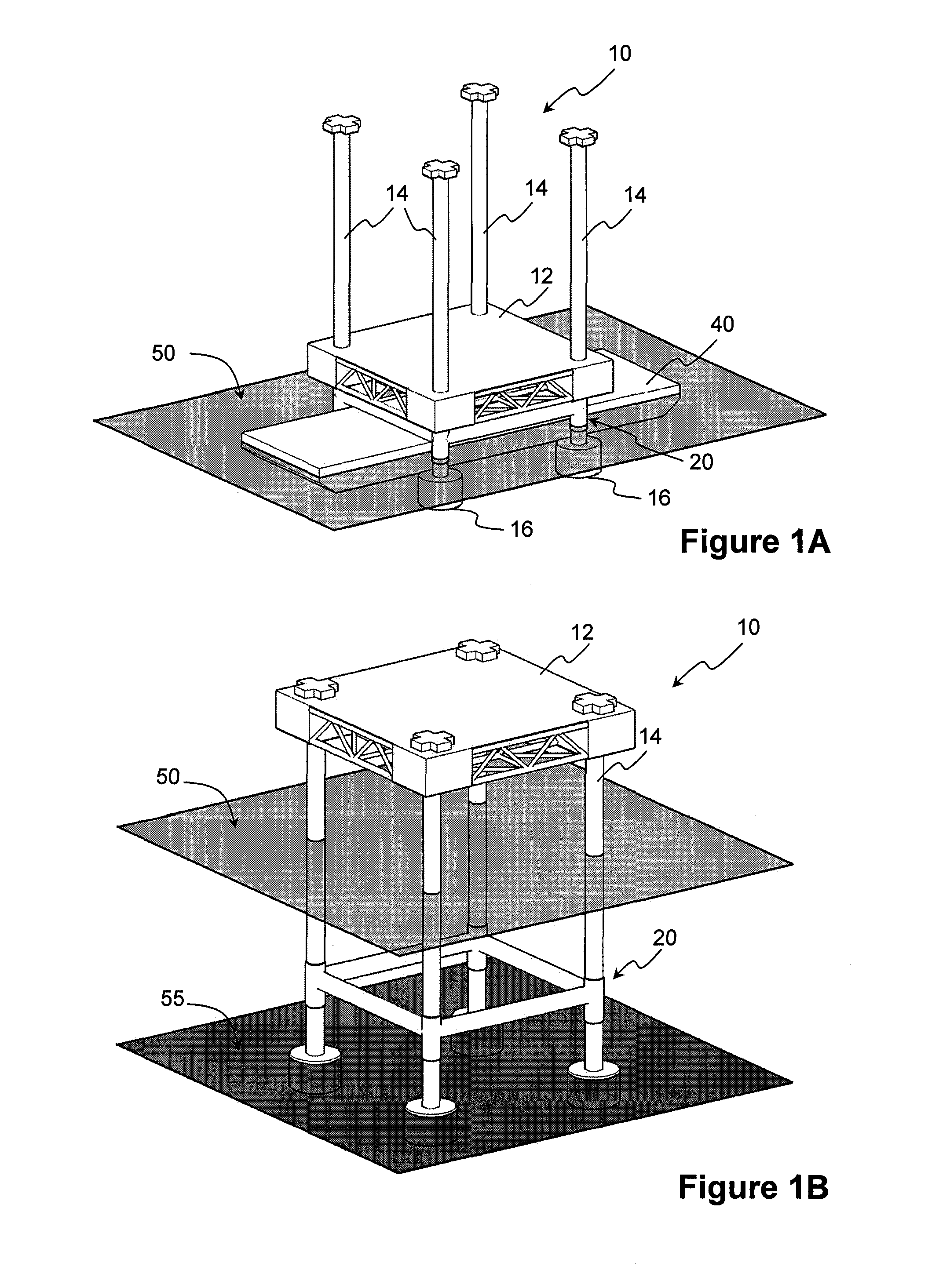
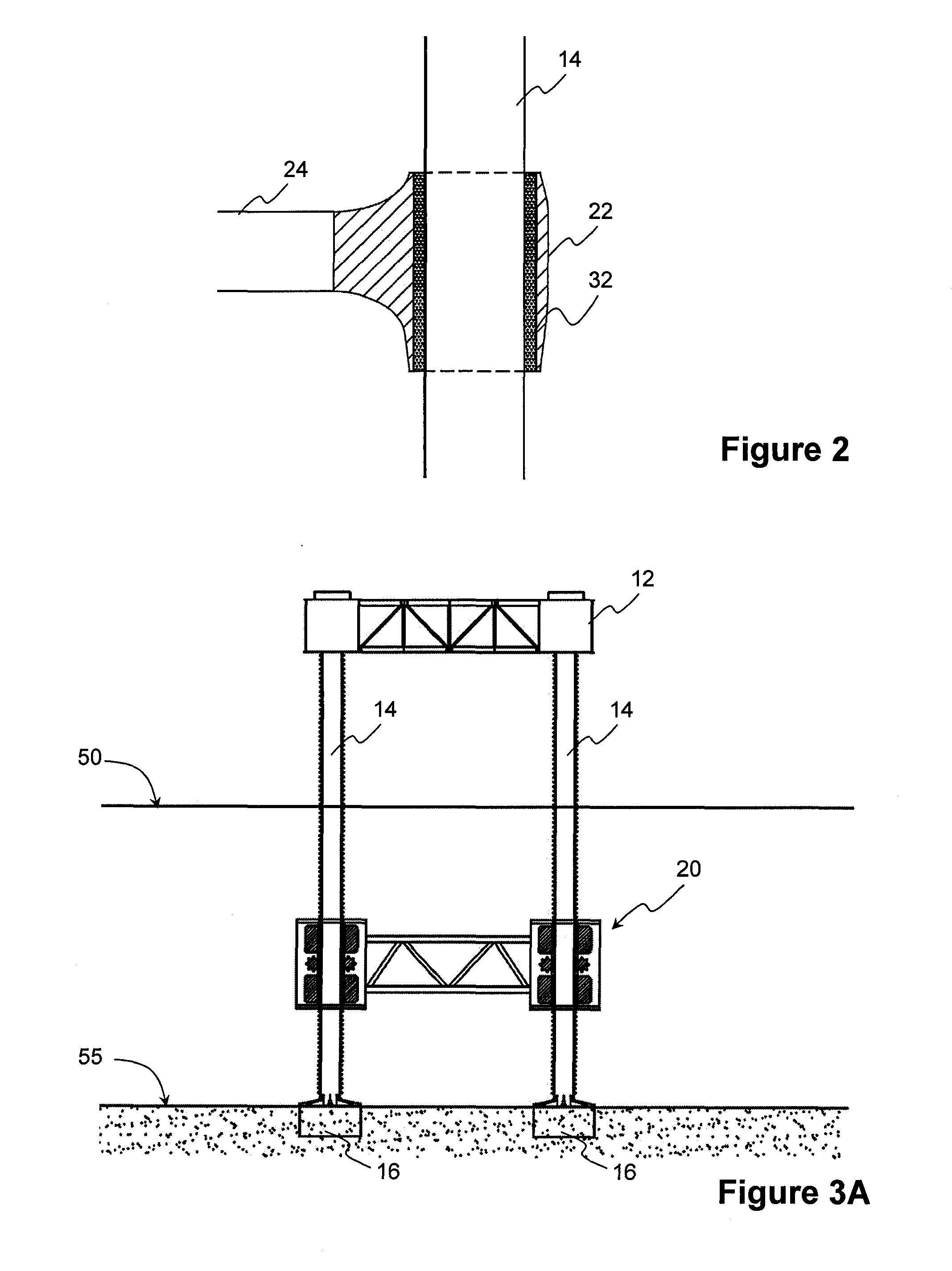
[0014]The self-installing platform may be pre-assembled before being transported to an offshore site for installation. At the offshore site, the plurality of legs of the self-installing platform may be lowered into the seabed. The brace frame may then be positioned at a desired elevation along the at least two of the plurality of legs and secured thereto. This way, rotational restraint is provided to significantly reduce leg stress and increase rigidity of the legs. With the increased rigidity, it has become possible to install platforms in relatively deep waters and harsh environments, and yet preventing large overall platform sway induced by adverse weather or sea conditions. As the brace frame is securable to the legs after the legs or footings are penetrated into or supported on the sea bed, differential penetration of legs or footings into the seabed is possible without risking large structural loads in the brace frame.

Problems solved by technology

Various methods of installing offshore platforms are available but have inherent problems.
This method is expensive due to limited availability and high operational and rental costs of the large floating cranes.
Accordingly, the platform can only be installed in relative shallow water and / or benign environments.
However, it is not possible to tow the platform on a barge as the presence of a barge supporting the platform would prevent lowering of the interconnected legs.
As such, the platform has to be specially designed to take the hydrostatic loads during tow and the small freeboard during tow renders the platform susceptible to green water.
If the differential penetration is too large, the bracings interconnecting the legs would experience large structural loads.
Consequently, this type of self-installing platform can only be installed on a flat seabed.
However, the movable conductor supports are meant to support the drill string and production conduit conductors, and would not improve the performance of the support legs.
However, various components of the structure have to be assembled at the offshore site which is a time-consuming and expensive process requiring floating cranes, and is therefore not a desirable alternative.

Method used


Image

  • Movable brace frame for self-installing platform
  • Movable brace frame for self-installing platform
  • Movable brace frame for self-installing platform

Examples


Embodiment Construction

[0027]In the following description, numerous specific details are set forth in order to provide a thorough understanding of various illustrative embodiments of the invention. It will be understood, however, to one skilled in the art, that embodiments of the invention may be practiced without some or all of these specific details. In other instances, well known process operations have not been described in detail in order not to unnecessarily obscure pertinent aspects of embodiments being described. In the drawings, like reference numerals refer to same or similar functionalities or features throughout the several views.

[0028]According to embodiments of the invention, in which a platform includes a hull and supporting legs, at least one brace frame is provided which is movable along at least two legs of a platform and securable to the legs at any elevation. Upon securing the brace frame to the legs that provide a support structure to the platform, the brace frame provides rotational ...


PUM


Abstract

Pre-assembled self installing platforms with improved performance due to additional rotational restraint to supporting legs and methods of installation. The platform includes a hull, legs movable relative to the hull, at least one brace frame movably connected to at least two of the legs. Upon installation, the brace frame may be positioned at a desired elevation and rigidly secured to the legs, providing rotational restraint to significantly reduce leg stress and increase rigidity of the legs. With the increased rigidity, it becomes possible to install platforms in relatively deep waters and harsh environments, and yet preventing large overall platform sway induced by adverse weather or sea conditions. As the brace frame is securable to the legs after the legs or footings are penetrated into or supported on the sea bed, differential penetration of legs or footings into the seabed becomes possible without risking large structural loads in the brace frame.

Description

BACKGROUND[0001]1. Technical Field[0002]Embodiments of the invention relate generally to apparatus and methods for improving the in place performance of a self-installing platform.[0003]2. Description of Related Art[0004]Various methods of installing offshore platforms are available but have inherent problems.[0005]One conventional method of installing fixed offshore platforms requires large floating cranes to lift and install a jacket structure onto the seabed, and subsequently lift and install a topside structure onto the installed jacket structure. This method is expensive due to limited availability and high operational and rental costs of the large floating cranes.[0006]Alternative to using large floating cranes, self-installing platforms have been developed. These self-installing platforms may be completely assembled at the yard and include movable legs which can be moved up and down relative to the hull using a (temporary) jacking system. The legs are disposed in a raised pos...

Claims


Application Information

Patent Timeline
Patent Type & Authority Applications(United States)
IPC IPC(8): E02B17/08
CPCE02B17/021E02B17/06E02B2017/0056E02B2017/0039E02B2017/0047E02B17/0818
Inventor HENSTRA, WOUTER JOACHIMPERRY, MICHAEL JOHNKRISDANI, HENRYFOO, KOK SENGQUAH, CHIN KAU MATTHEW
Owner KEPPEL OFFSHORE & MARINE TECH CENT PTE LTD
Learn More