Fast edge routing for interactive diagramming

a diagramming and interactive technology, applied in the field of fast edge routing for interactive diagramming, can solve the problems of inability to construct the full tangent-visibility graph, inability to scale, and inability to solve quadratic (in the number of nodes) routing schemes, etc., to achieve fast routing, more scalable and interactive edge, and quick generation of sparse visibility graphs

Active Publication Date: 2011-12-15
MICROSOFT TECH LICENSING LLC
View PDF1 Cites 15 Cited by
  • Summary
  • Abstract
  • Description
  • Claims
  • Application Information

AI Technical Summary

Benefits of technology

[0004]An edge routing system is described herein that uses a spatial decomposition to achieve faster routing, and more quickly generates a sparse visibility graph using a cone spanner. The system provides two approaches that can be used separately or in combination to achieve faster—and hence more scalable and more interactive—edge routing using approximate shortest paths. The first approach uses a spatial decomposition of the nodes in a graph, moving them slightly to obtain strictly disjoint convex hulls around groups of nodes, and then computing visibility graphs over these composite hulls rather than individual nodes. The second approach generates a sparse visibility-graph spanner to accelerate the process of producing the visibility graph. The two techniques are complementary, that is they can be used together to obtain even faster routing. The system allows high quality obstacle avoiding edge routing for large diagrams (with hundreds or thousands of nodes) or in interactive diagramming applications where very fast refreshes of routing are used with many nodes moving at the same time.

Problems solved by technology

However, construction of the full tangent-visibility graph is computationally expensive, at least quadratic time in the number of nodes.
This makes such existing tangent-visibility-graph routing schemes infeasible for interactive diagramming applications involving large diagrams with hundreds or thousands of nodes.
However, the popular force-directed family of layout algorithms for general undirected graphs does not usually consider routing edges around node hulls (except perhaps as a post-processing step).
For graphs with hundreds of nodes, the quadratic (in the number of nodes) or worse computational cost of constructing the visibility graph can be too slow, especially for interactive applications where the layout is changing significantly from iteration to iteration.

Method used


Image

  • Fast edge routing for interactive diagramming
  • Fast edge routing for interactive diagramming
  • Fast edge routing for interactive diagramming

Examples


Embodiment Construction

>FIG. 6 illustrates edges created by one sweep during cone spanning, in one embodiment.

[0012]FIG. 7 illustrates types of sweepline events in further detail, in one embodiment.

[0013]FIG. 8 illustrates cone closure events and missing broken sides, in one embodiment.

DETAILED DESCRIPTION

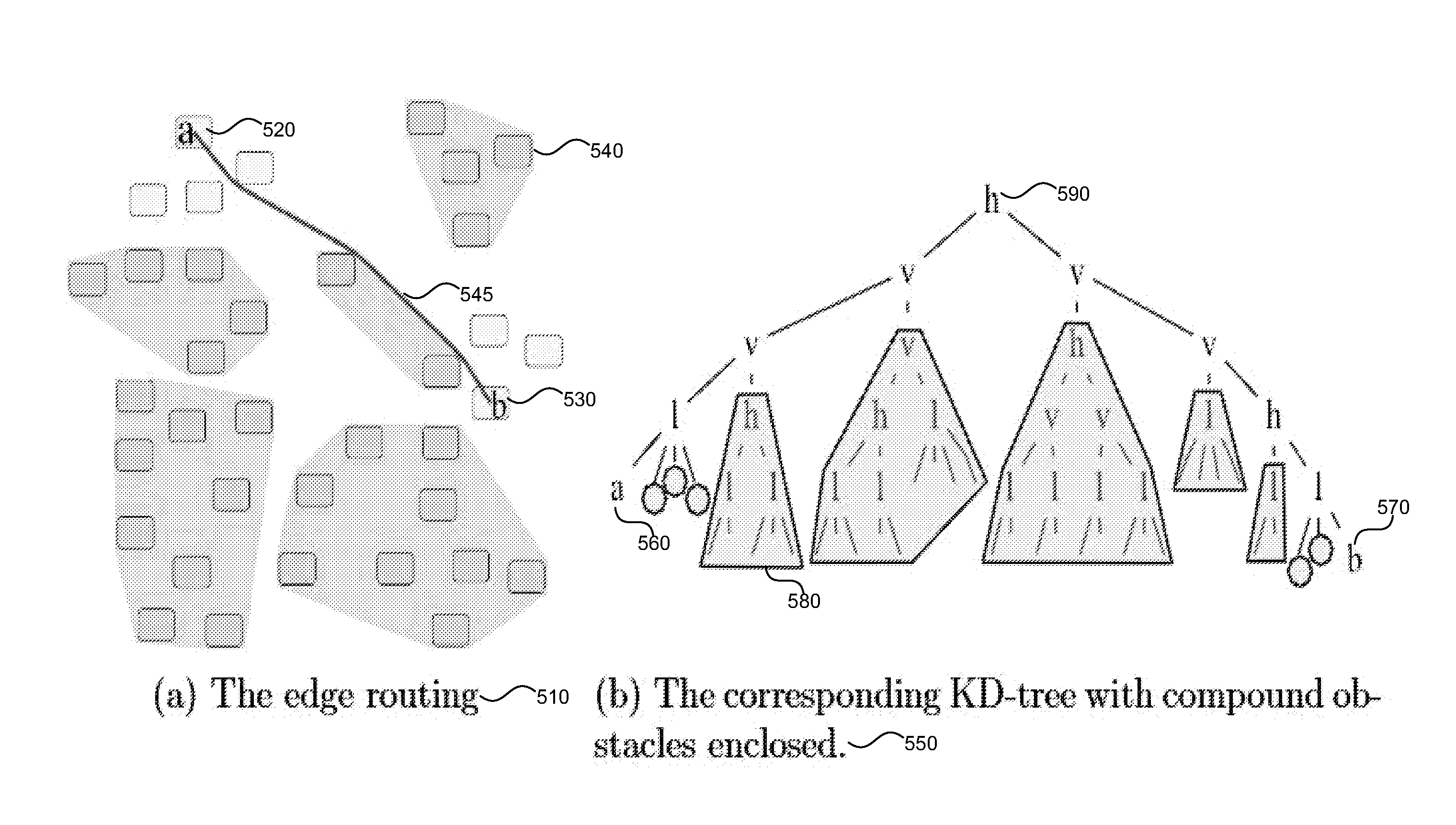
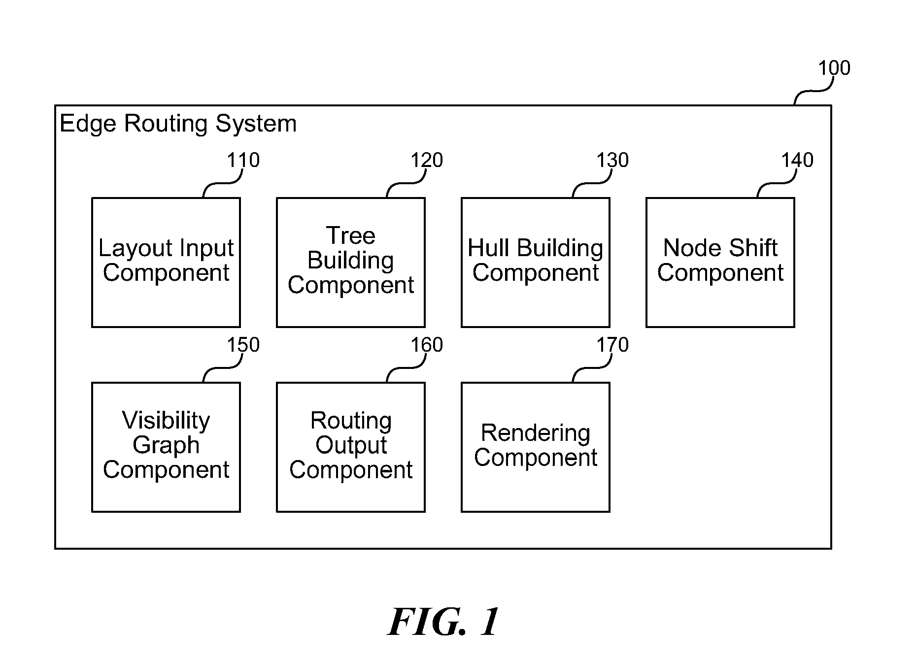
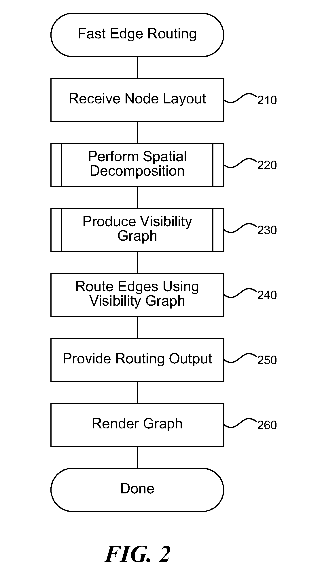
[0014]An edge routing system is described herein that uses a spatial decomposition to achieve faster routing, and more quickly generates a sparse visibility graph using a cone spanner. The system provides two approaches that can be used separately or in combination to achieve faster—and hence more scalable and more interactive—edge routing using approximate shortest paths. The first approach uses a spatial decomposition of the nodes in a graph, moving them slightly to obtain strictly disjoint convex hulls around groups of nodes, and then computing visibility graphs over these composite hulls rather than individual nodes. The second approach generates a sparse visibility-graph spanner to accelerate the pr...


PUM


Abstract

An edge routing system is described herein that uses a spatial decomposition to achieve faster routing, and more quickly generates a sparse visibility graph using a cone spanner. The system provides two approaches that can be used separately or in combination to achieve faster—and hence more scalable and more interactive—edge routing using approximate shortest paths. The first approach uses a spatial decomposition of the nodes in a graph, moving them slightly to obtain strictly disjoint convex hulls around groups of nodes, and then computing visibility graphs over these composite hulls rather than individual nodes. The second approach generates a sparse visibility-graph spanner to accelerate the process of producing the visibility graph. The system allows high quality obstacle avoiding edge routing for large diagrams in interactive diagramming applications where very fast refreshes of routing are used with many nodes moving at the same time.

Description

BACKGROUND[0001]Most network diagrams (graphs) that people use for visualization of various concepts have nodes with associated textual or graphical content. For example, in Unified Modeling Language (UML) class diagrams nodes are drawn as boxes with textual content describing class attributes or methods. As another example, in metabolic pathway diagrams nodes representing chemical compounds may have long textual labels or a graphic representation of the molecular structure.[0002]Routing refers to paths taken by connectors to connect nodes. If edges (connectors) that are not directly connected to a particular node are drawn over that node then the label may be obscured. Alternately, if edges are drawn behind a node then the reader may erroneously assume a connection exists to the node. Routing edges around nodes avoids this ambiguity. Therefore, to automatically produce high quality drawings of network diagrams it is important to find routes for the edges that do not intersect node ...

Claims


Application Information

Patent Timeline
Patent Type & Authority Applications(United States)
IPC IPC(8): G06F3/048
CPCG06T11/206
Inventor DWYER, TIMOTHY G.NACHMANSON, LEV
Owner MICROSOFT TECH LICENSING LLC
Why Eureka
Try Eureka