Blade-switchable utility knife

Active Publication Date: 2011-12-22
HO CHUN FENG
View PDF16 Cites 29 Cited by
  • Summary
  • Abstract
  • Description
  • Claims
  • Application Information

AI Technical Summary

Benefits of technology

[0008]Accordingly, an object of the present invention is to provide a blade-switchable utility knife having advantages and effects of quick switch of blades for u

Problems solved by technology

Unfortunately, conventional utility knifes can only be equipped with one blade for use.
When the blade becomes worn out and dull in use or different blades are in need, it is necessary to replace the original blade with another blade by detaching the original blade from the blade sliding holder and replacing with another blade.
It is

Method used


Image

  • Blade-switchable utility knife
  • Blade-switchable utility knife
  • Blade-switchable utility knife

Examples


Embodiment Construction

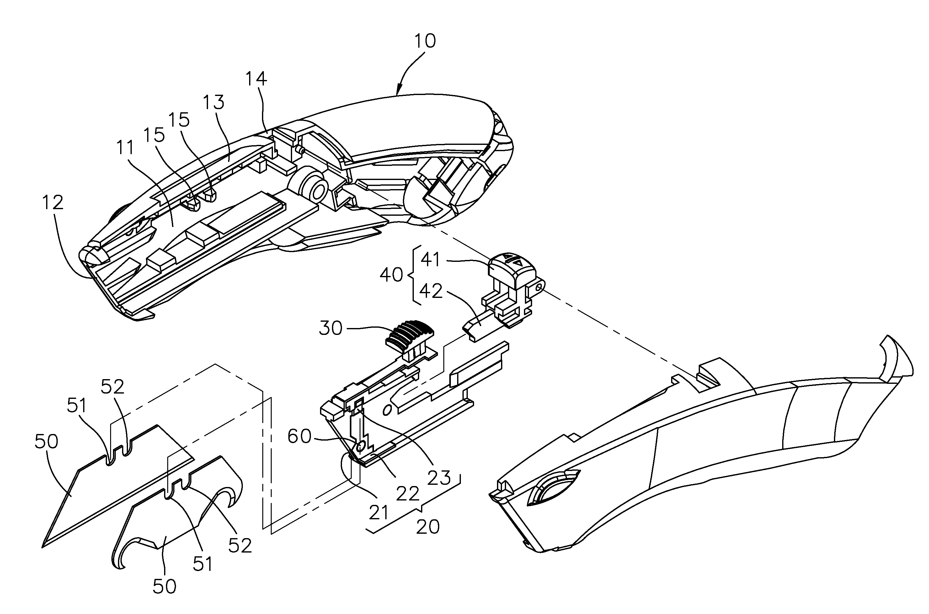
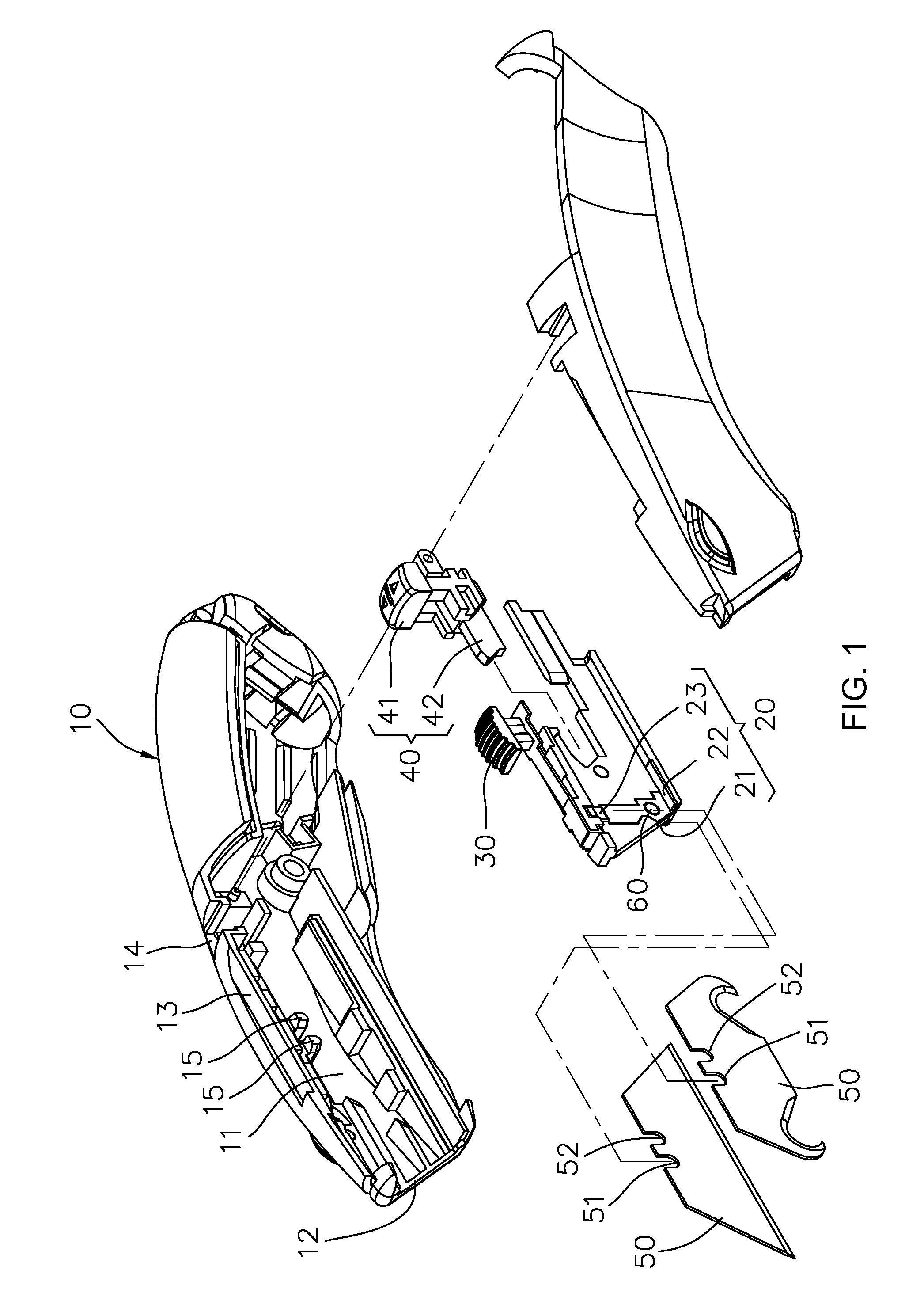
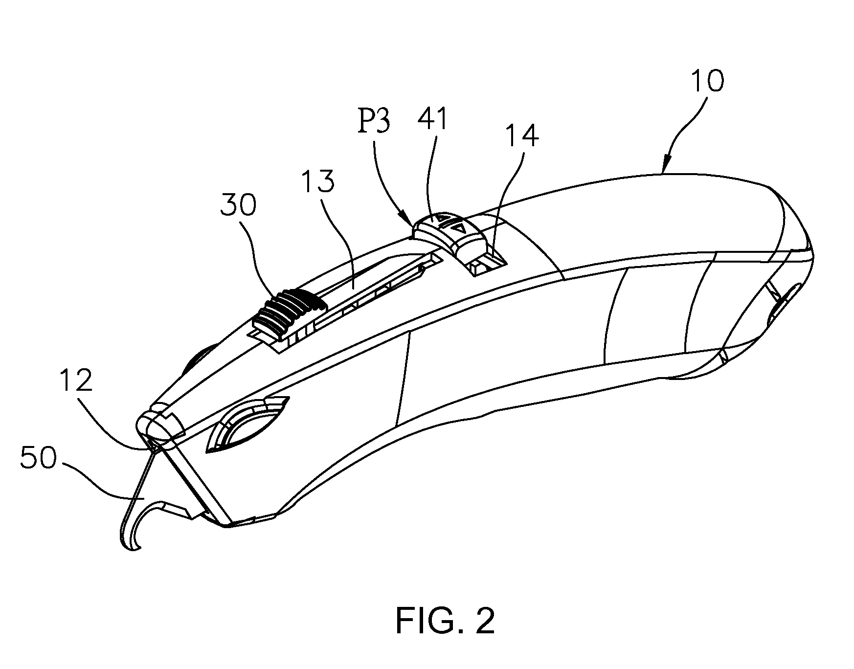
[0033]Referring to FIG. 1 to FIG. 6B, a blade-switchable utility knife of the present invention of the present invention comprises a housing 10 defining an internal space 11, an opening 12, a sliding slot 13, a switch groove 14, a pair of first limit portions 15 and a pair of second limit portions 16 therein.

[0034]A blade slider 20 is received in the internal space 11 of the housing 10 to be slidably moving backwards and forwards within the internal space 11. The blade slider 20 can be at least moved to a blade retraction (first moving) position P1 and a blade protrusion (second moving) position P2. The blade slider 20 comprises a first blade compartment 21 and a second blade compartment 22, and a fixing bulge 23 is formed in each of the first and second blade compartments 21, 22. A width of the opening 12 is equal to (or slightly larger than) a width of the blade slider 20 plus a width of a pair of blades 50.

[0035]A slide actuator 30 is fixedly disposed on the blade slider 20 and i...


PUM


Abstract

A blade-switchable utility knife of the present invention comprises a housing, a blade slider, a slide actuator, a switch actuator, a pair of blades and a pair of restoring elements. By manipulating the switch actuator, one of the pair of blades is capable of moving together with the blade slider. Accordingly, the present invention has advantages and effects of quick switch of the blades for use and convenient carrying.

Description

BACKGROUND OF THE INVENTION[0001]1. Field of the Invention[0002]The present invention relates to a switchable utility knife, and particularly to a blade-switchable utility knife having advantages of quickly switching blades for use and carrying conveniently, etc.[0003]2. Related Art[0004]Conventional utility knifes generally are designed to have a blade fixed to a blade sliding holder so as to allow the blade to be extendable out of a shell of the utility knife or retractable therein via moving of the blade sliding holder.[0005]Unfortunately, conventional utility knifes can only be equipped with one blade for use. When the blade becomes worn out and dull in use or different blades are in need, it is necessary to replace the original blade with another blade by detaching the original blade from the blade sliding holder and replacing with another blade. It is rather inconvenient for use.[0006]Furthermore, it is rather inconvenient and time-consuming to replace a blade in the abovement...

Claims


Application Information

Patent Timeline
IPC IPC(8): B26B1/08B26B5/00
CPCB26B5/003B26B5/001
Inventor HO, CHUN-FENG
Owner HO CHUN FENG
Why Eureka
Try Eureka