
Footwear With Integrated Biased Heel Fit Device

a heel device and heel technology, applied in the field of heel devices for athletic footwear, can solve the problems of abrasion and blisters, the overall proportion of a shoe designed for a male foot not always providing the best fit on a majority of female feet, etc., and achieve the effect of enhancing the biasing effect of the heel devi

Active Publication Date: 2011-12-22
NIKE INC
View PDF10 Cites 14 Cited by
  • Summary
  • Abstract
  • Description
  • Claims
  • Application Information

AI Technical Summary

Benefits of technology

The present invention provides a shoe structure that can fit a wider range of feet widths and proportions, particularly for females. The shoe has a resilient heel device with opposing portions that securely fit the heel and Achilles area of the wearer's foot. The heel device can be a single molded piece or a combination of multiple pieces operating as one. The shoe also includes an upper, insole, cushioning midsole, and ground-engaging outsole, and the heel device is integrated into the shoe. The heel device has biased opposing portions attached to the upper and an integrated bridge portion underlying the upper and attached between the upper and the midsole. The heel device can be a two-piece element with an interlocking configuration or a smaller size than the heel area of the shoe. The technical effects of the invention include improved fit, comfort, and stability for a wide range of foot sizes.

Problems solved by technology

Even though the human foot is a complex engineering marvel with a great degree of variability from person to person, conventional fittings only use that single width measurement.
Although width sizing helps with fit, the overall proportions of a shoe designed for a male foot does not always provide the best fit on a majority of female feet.
These types of devices can themselves be the cause of problems and even lead to injuries such as abrasion and blisters, particularly when used in athletic footwear in which the user subjects the shoes to higher impacts, quicker stops and starts and turns as compared to dress shoes.

Method used


Image

  • Footwear With Integrated Biased Heel Fit Device
  • Footwear With Integrated Biased Heel Fit Device
  • Footwear With Integrated Biased Heel Fit Device

Examples


Embodiment Construction

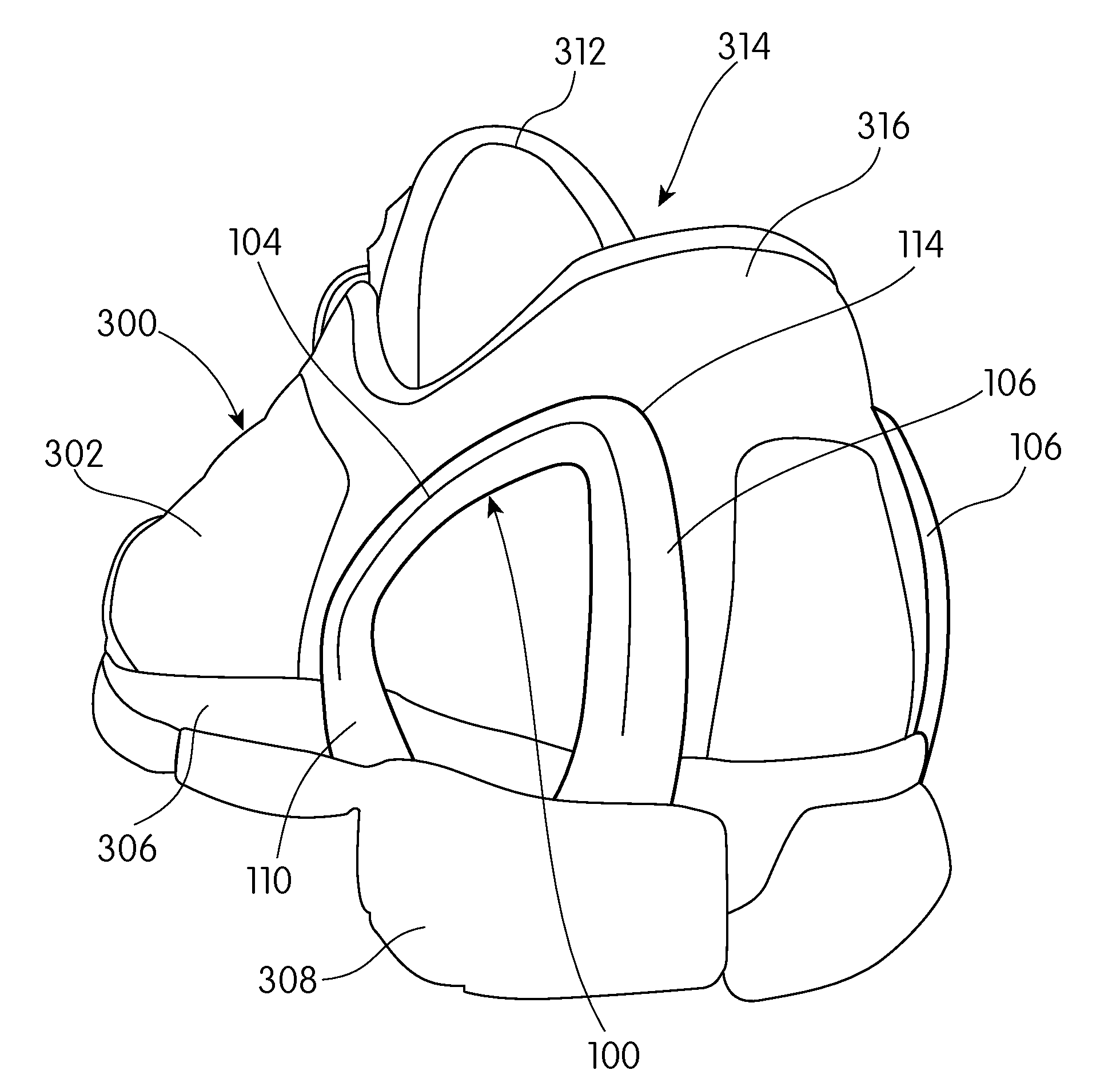
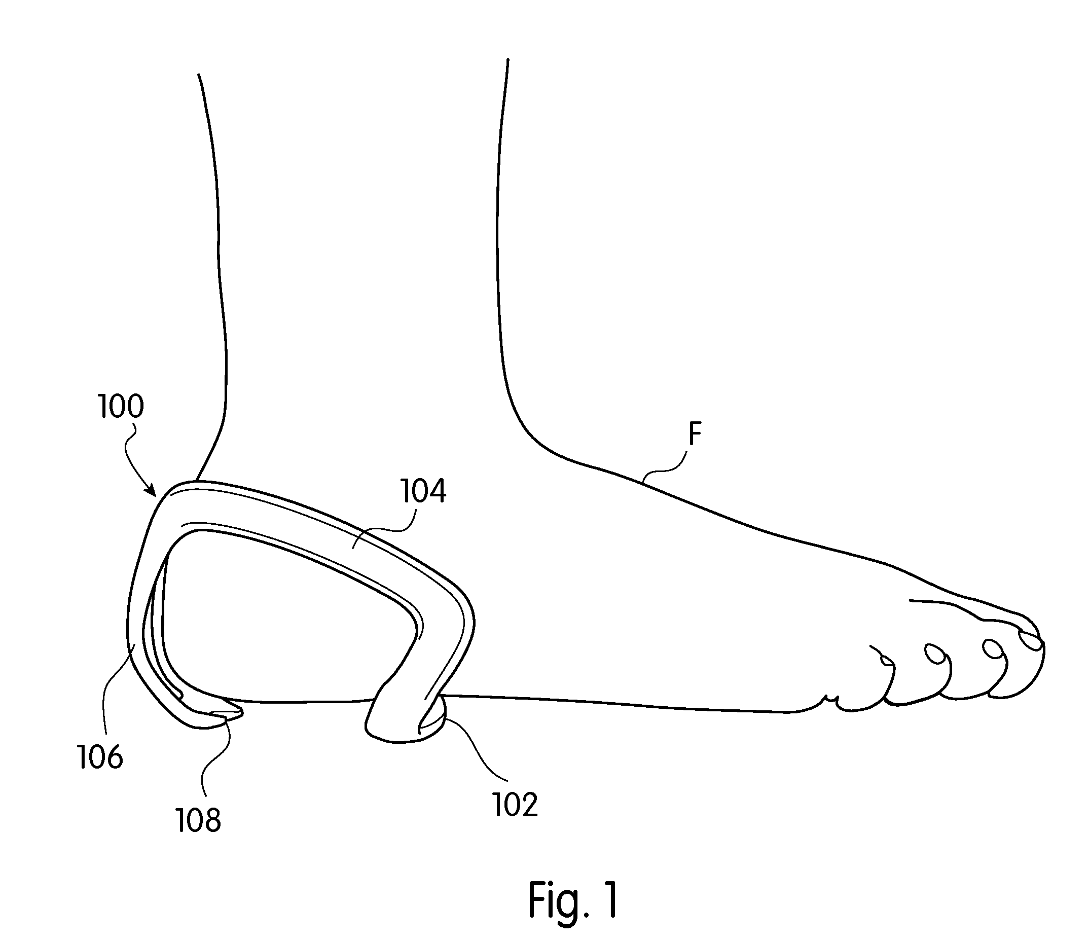
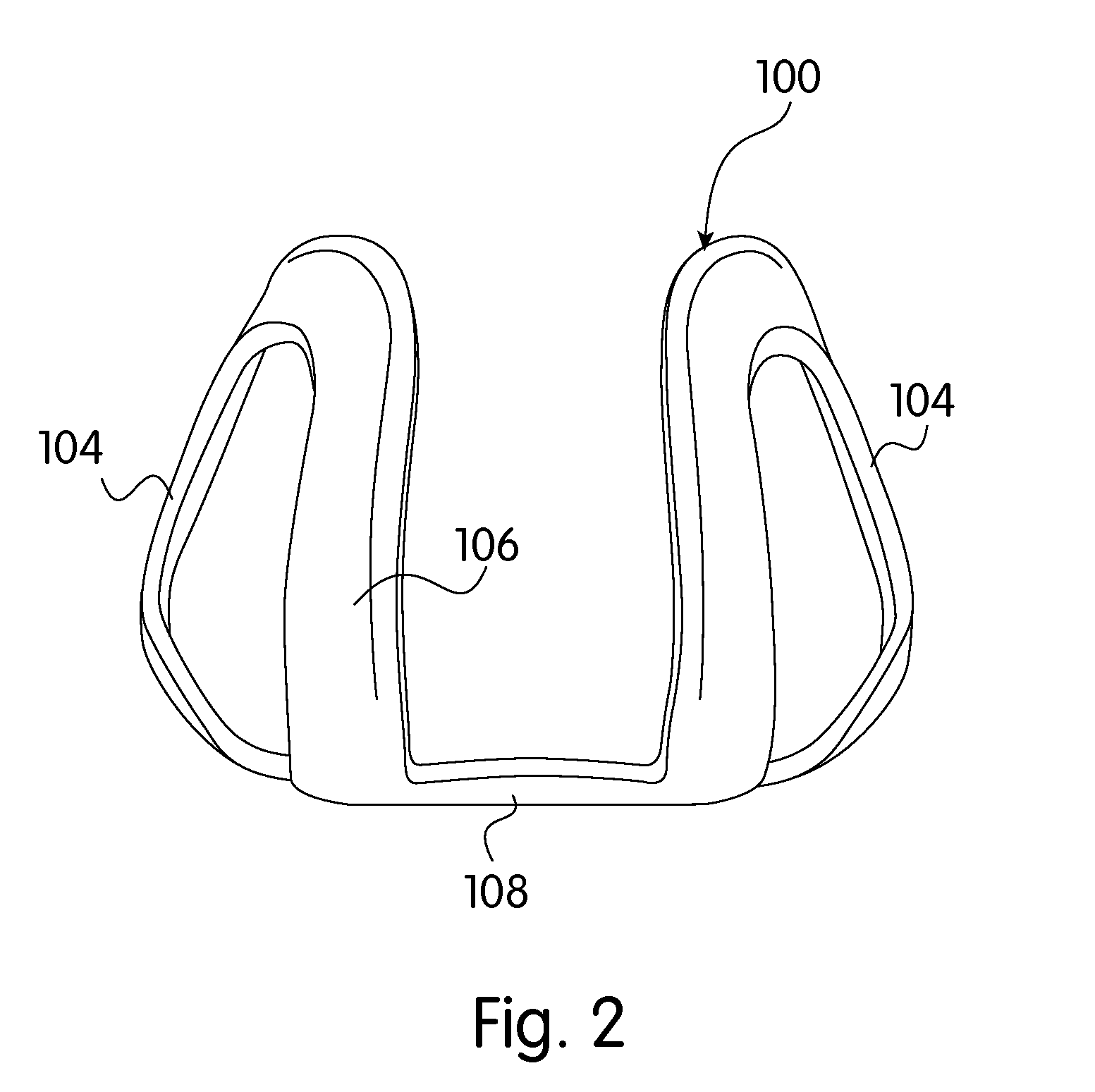
[0039]Resilient heel device 100 is shown schematically on a foot F in FIGS. 1 and 3, and in isolation in FIG. 2. These views along with FIG. 10 are intended to show how the heel device is placed relative to the anatomy of the foot. It should be understood however, that the heel device is not necessarily a separate piece or accessory and would generally not be used as shown in these figures. The present invention contemplates that the heel device will be incorporated into a shoe and will become part of the structure of the shoe as seen later in FIGS. 11-13. An alternative embodiment of the heel device of the present invention which is comprised of two pieces is illustrated in FIGS. 14-16. An example of a commercial product embodying the present invention is the Nike™ 100 D-Gris Women's Running Shoe.

[0040]Referring to FIGS. 1-3, heel device 100 is formed of a resilient material and comprises a bottom bridge portion 102 extending underneath the foot. Along each side of the foot, the he...


PUM

PropertyMeasurementUnit
stabilityaaaaaaaaaa
thicknessaaaaaaaaaa
transition angleaaaaaaaaaa

Abstract

A shoe structure specifically designed to more securely fit a wider range of feet widths and proportions by providing an integrated resilient heel device in the rearfoot region of the upper. The heel device extends upward and rearward toward the back of the foot to avoid the bulbous end of the calcaneus but also to engage the area just above the heel bone. The heel device has opposing portions that are biased toward one another and provide a secure but comfortable engagement of the shoe onto the wearer's heel. The heel device is smaller than the size of the shoe into which it is incorporated to enhance the biasing effect of the opposing portions.

Description

CROSS-REFERENCE TO RELATED APPLICATION(S)[0001]This application is a divisional of co-pending U.S. patent application Ser. No. 11 / 696,733 (Attorney Docket No. 51-1020), filed Apr. 5, 2007 and issued on ______ as U.S. Pat. No. ______, the entirety of which is hereby incorporated by reference.BACKGROUND[0002]1. Field of the Invention[0003]This invention relates to a heel element for footwear, and more particularly to a resilient heel device for athletic footwear designed to provide a secure anatomically appropriate fit for a larger range of foot sizes and shapes.[0004]2. Background of the Invention.[0005]The design of most athletic footwear is directed to its performance and takes into account the intended use of the shoe such as the type of activity or playing surface. For example, mid or high top ankle collars are provided for activities that may involve jumping so as to stabilize and support the ankles of the wearer. Likewise, the degree of cushioning is determined by the intended ...

Claims


Application Information

Patent Timeline
Patent Type & Authority Applications(United States)
IPC IPC(8): A43B23/08
CPCA43B23/17A43B7/28
Inventor SOKOLOWSKI, SUSAN
Owner NIKE INC
Learn More