
Holding case for portable electronic devices

a technology for electronic devices and devices, applied in the field of holding mechanisms, can solve the problems of affecting the use of the device, the device is extremely bulky and cumbersome, and the entire hand, and achieve the effect of convenient use and convenient position

Pending Publication Date: 2011-12-22
ROBERTS KYLE
View PDF7 Cites 110 Cited by
  • Summary
  • Abstract
  • Description
  • Claims
  • Application Information

AI Technical Summary

Benefits of technology

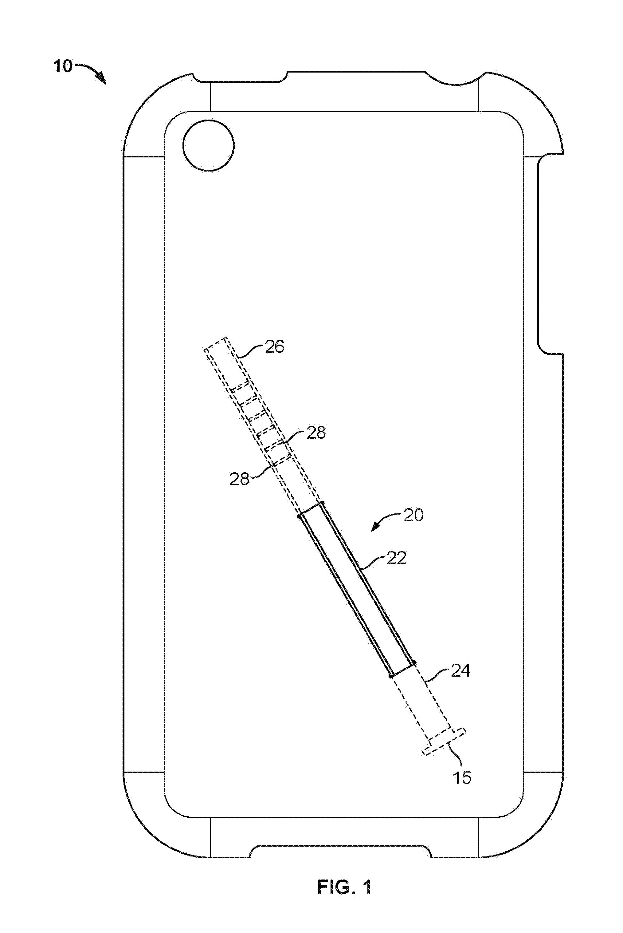
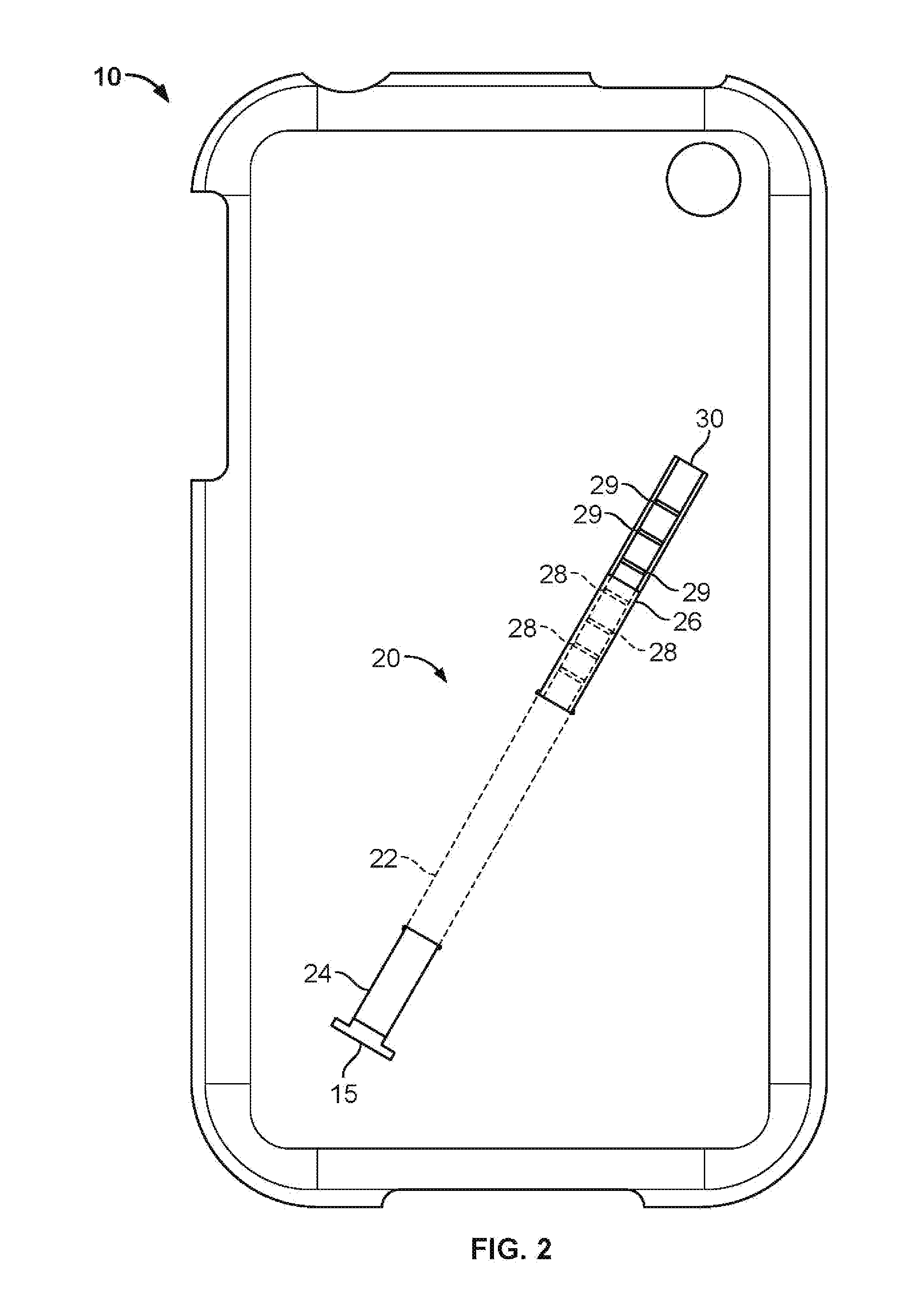
[0005]The presently disclosed holding case allows a user to hold a portable electronic device with a single finger, allowing the user to keep the device in a convenient and handy position for use. The device comprises a flat, flexible strap, which fits along the backing to a device or device case. The strap adjustably slides into two slots placed on opposing sides of the case. On the underside of the device casing or backing, the strap slides along a raised track. One end of the strap further comprises horizontal ridges across its tail portion, which click into either matching grooves or conversely shaped ridges in the case track. This permits the strap to be temporarily locked to various degrees in an open position for reception of any finger and securely hold a device in place. When not in use, a slight touch causes the strap to retract back to its default flat position. The mechanism provides enough tension around a finger so that the device stays in place, for example when pressing keys, but enough flexibility to rotate the case.

Problems solved by technology

Currently, some devices have handles, which requires an entire hand, but some phones and mp3 players don't even have a place to hold them.
These devices are extremely bulky and cumbersome, especially when holding for extended lengths of time or trying to remove from a case or pocket.
Yet all of these models overlook the central problem of keeping the device in a functional position while not commandeering use of the entire hand.

Method used


Image

  • Holding case for portable electronic devices
  • Holding case for portable electronic devices
  • Holding case for portable electronic devices

Examples


Embodiment Construction

[0012]In the following description of the various embodiments, reference is made to the accompanying drawings, which form a part hereof, and in which is shown by way of illustration, various embodiments in which the invention may be practiced. It is to be understood that other embodiments may still be utilized and structural and functional modifications may be made without departing from the scope and spirit of the present invention.

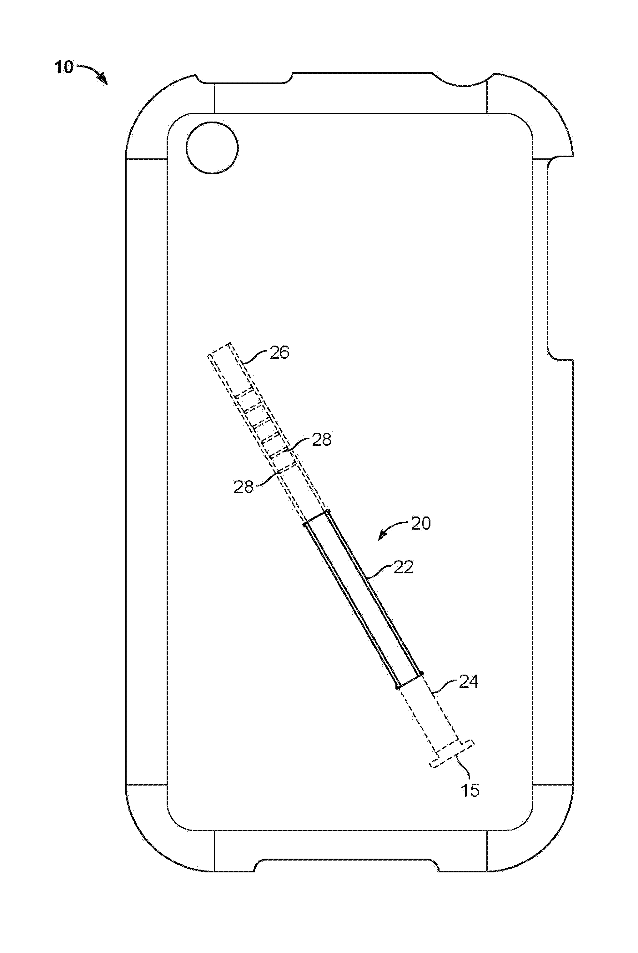
[0013]Referring to FIG. 1, the preferred embodiment of the top of holding case 10 is shown. Holding case 10 comprises rectangular elastic strap 20 which is inserted into two slots in case 10 to form finger gripping portion 22 on the top of case 10. Gripping portion 22 is made to be pulled upward in order to fit around a finger, digit, elongate article or the like. In one embodiment, gripping portion 22 may be coated or etched to produce a higher friction area of strap 20 or tacky. surface. Additionally, gripping portion 22 may be thicker or padded becaus...


PUM


Abstract

The presently disclosed holding case allows a user to hold a portable electronic device with a single finger, allowing the user to keep the device in a convenient and handy position for use. The device comprises a flat, flexible strap which fits along the backing to a device or device case. The strap adjustably slides into two slots placed on opposing sides of the case. On the inside of the device casing or backing, the strap slides along a raised track. One end of the strap further comprises horizontal ridges across its tail portion, which partially lock into matching grooves in the case. This permits the strap to be temporarily locked in an open position for reception of any finger and to securely hold a device in place. When not in use, a slight touch causes the strap to retract back to its default flat position.

Description

FIELD OF INVENTION[0001]The present invention relates to the fields of portable electronic devices and device cases. More specifically, the invention relates to a holding mechanism to be used with portable electronic devices and device cases.BACKGROUND OF THE INVENTION[0002]Portable electronic devices, such as cellular telephones, personal digital assistants (PDAs), mini-laptops and mP3 players have existed in our popular culture and business culture for many years now. The technology behind the devices continues to advance at an exponential rate, yet important features of the devices themselves, primarily the body structure, coverings, and cases, have been widely overlooked from a functional standpoint. Regardless of the internal capabilities of a device, every one of them must be picked up and handled at some point during each and every usage. This is usually true even when employing Bluetooth or headsets. With the growing number of applications and multi-tasking capabilities on m...

Claims


Application Information

Patent Timeline
IPC IPC(8): B65D85/00
CPCA45C2011/002A45F5/00H04M1/04A45F2200/0516H04B1/3888A45F2005/008
Inventor ROBERTS, KYLE
Owner ROBERTS KYLE
Learn More