
Apparatus and method to correct image

a technology of apparatus and image, applied in the field of methods and apparatus to correct images, can solve the problems of depth value error, distortion of measured depth value, etc., and achieve the effect of rapid calibration of object images, accurate and rapid correction of the plurality of depth values

Active Publication Date: 2011-12-22
SAMSUNG ELECTRONICS CO LTD
View PDF9 Cites 39 Cited by
  • Summary
  • Abstract
  • Description
  • Claims
  • Application Information

AI Technical Summary

Benefits of technology

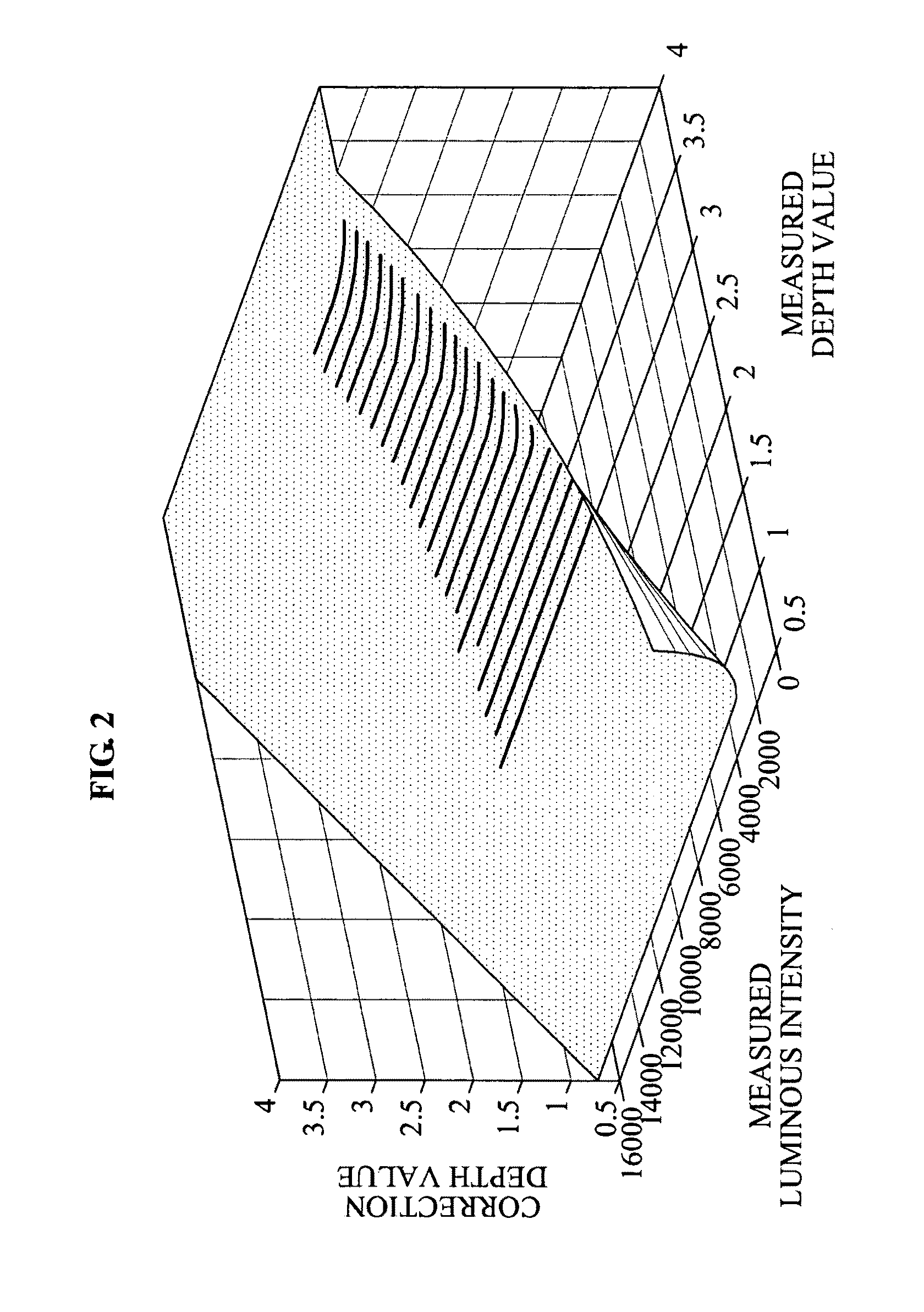
[0021]According to embodiments, it is possible to correct errors of depth values based on correction depth values stored in the form of a LUT, with great accuracy and reliability. Here, the errors of depth values may occur caused by a measurement distance and an intensity of reflected infrared (IR) light measured by a sensor of a depth photography apparatus.
[0022]Correction depth values may be obtained based on a distance between an object and a depth photography apparatus, may be mapped to a plurality of luminous intensities and a plurality of depth values, and may be stored. Thus, it is possible to more accurately and rapidly correct the plurality of depth values.
[0023]Also, information used to calibrate a relative location and direction between a plurality of depth photography apparatuses may be stored in advance, and thus it is possible to rapidly calibrate object images captured by different photography apparatuses, and also possible to exactly match the object images with each other.
[0024]In a multi-view capturing system where a depth photography apparatus and a color photography apparatus are used, information on a change relationship between the depth photography apparatus and the color photography apparatus may be calculated in advance and the calculated information may be stored, and it is therefore possible to exactly match a 3D shape of an object with color information.

Problems solved by technology

However, the depth camera may measure a depth based on the TOF information, and thus a distortion of the measured depth value may occur due to the measured distance between the object and the depth camera, and an intensity of a reflected light.
Here, the errors of depth values may occur caused by a measurement distance and an intensity of reflected infrared (IR) light measured by a sensor of a depth photography apparatus.

Method used


Image

  • Apparatus and method to correct image
  • Apparatus and method to correct image
  • Apparatus and method to correct image

Examples


Embodiment Construction

[0035]Reference will now be made in detail to at least one example embodiment, examples of which are illustrated in the accompanying drawings, wherein like reference numerals refer to the like elements throughout. Example embodiments are described below to explain the present disclosure by referring to the figures.

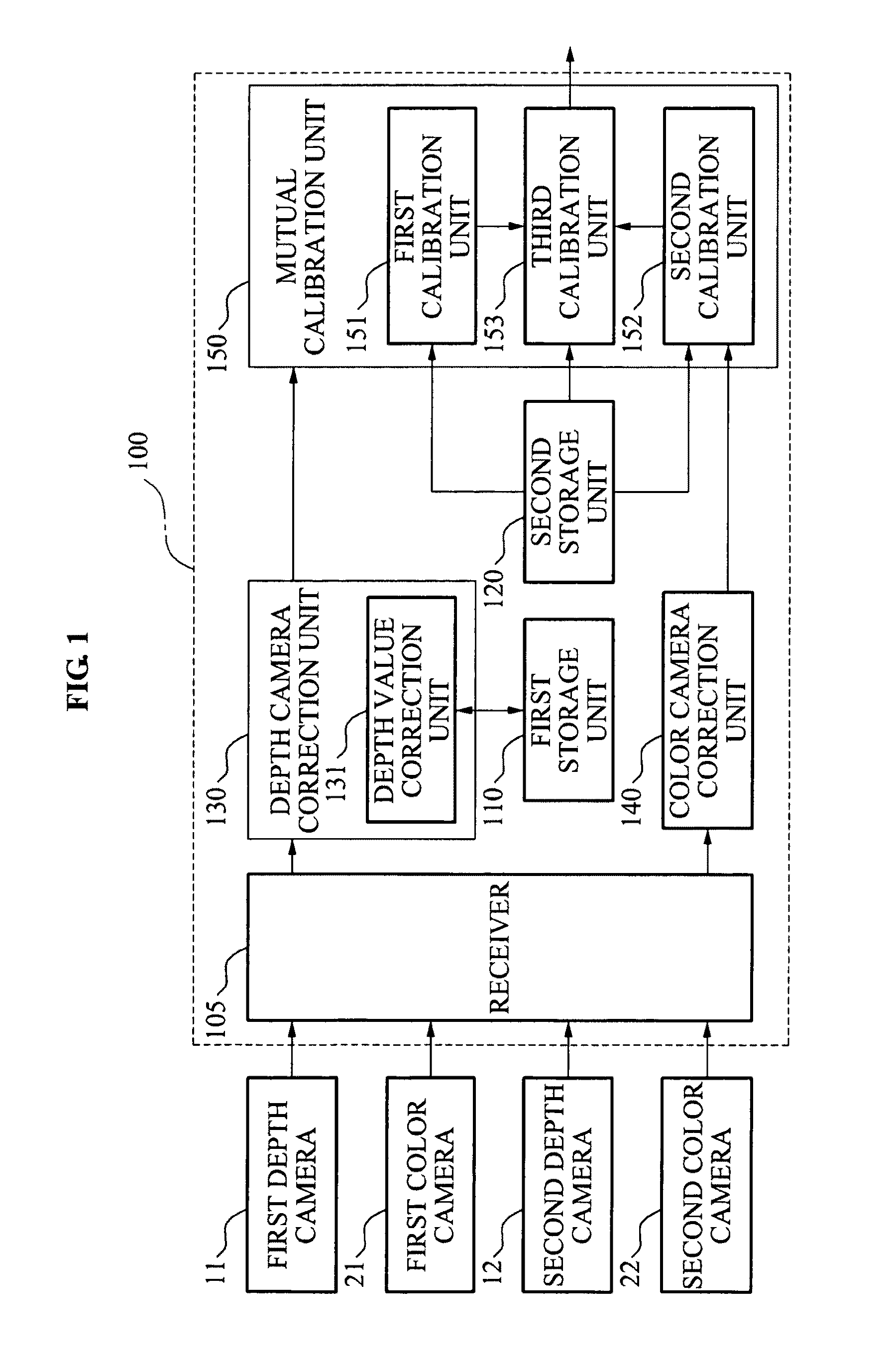
[0036]FIG. 1 illustrates a block diagram of an image correction apparatus 100 according to at least one example embodiment.

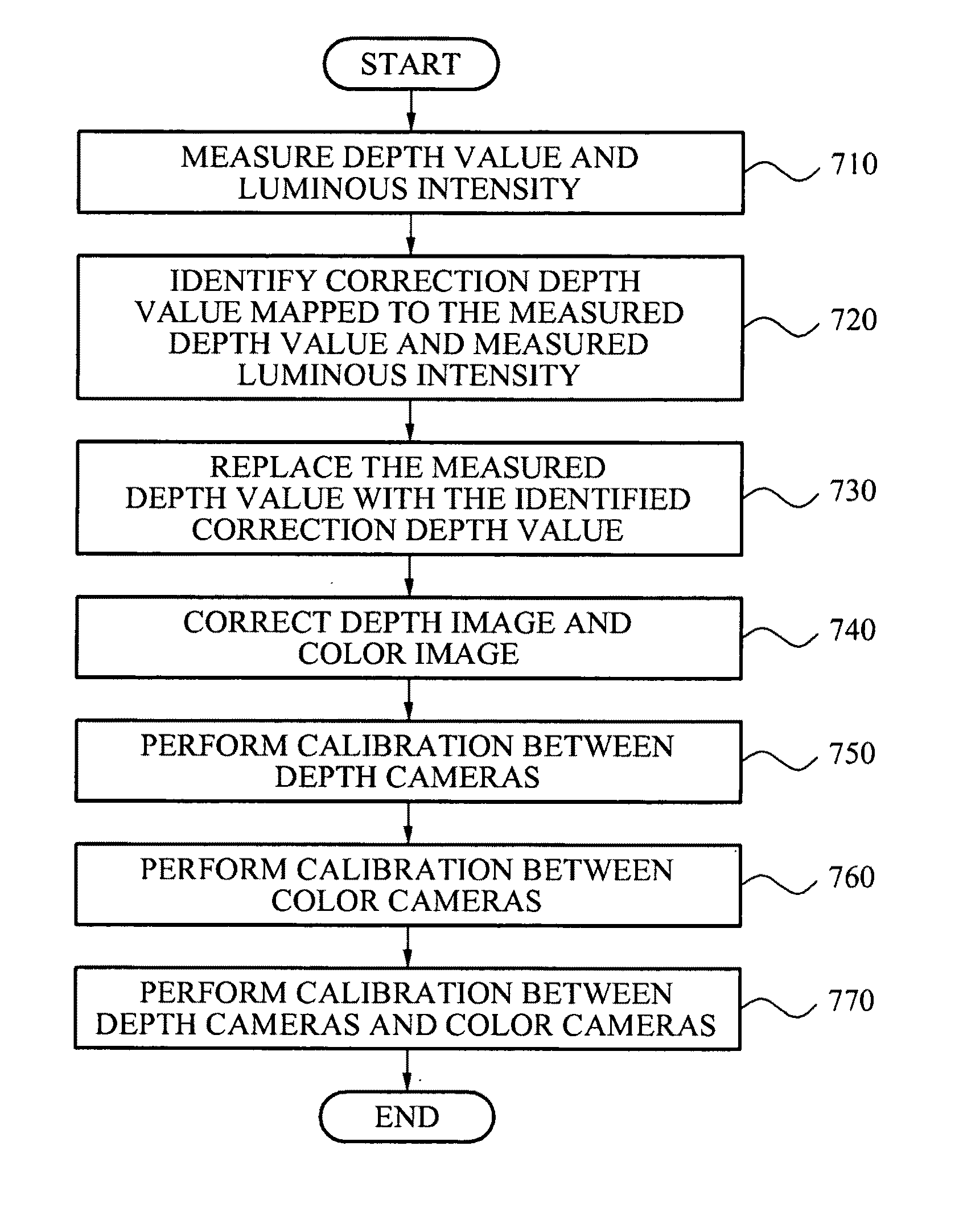
[0037]The image correction apparatus 100 of FIG. 1 may correct depth values of depth images and depth values of brightness images, and may calibrate a relative location and direction between each of the images. The depth images and brightness images are acquired using a plurality of depth photography apparatuses and a plurality of color photography apparatuses.

[0038]To measure a Time of Flight (TOF), a depth photography apparatus may irradiate a light source, such as infrared rays (IR), onto an object, and may detect a light reflected from the object u...


PUM


Abstract

An apparatus and method of correcting an image are provided. The apparatus includes a receiver to receive a depth value and a luminous intensity, the depth value and the luminous intensity being measured by at least one depth sensor, and a correction unit to read a correction depth value of a plurality of correction depth values mapped to different depth values and different luminous intensities from a first storage unit and to correct the measured depth value using the read correction depth value, the correction depth value being mapped to the measured depth value and the measured luminous intensity.

Description

CROSS-REFERENCE TO RELATED APPLICATIONS[0001]This application claims the benefit of Korean Patent Application No. 10-2009-0109769, filed on Nov. 13, 2009, in the Korean Intellectual Property Office, the disclosure of which is incorporated herein by reference.BACKGROUND[0002]1. Field[0003]Example embodiments of the following description relate to a method and apparatus to correct an image that may correct distortion of a depth value occurring due to a measured distance and a measured luminous intensity.[0004]2. Description of the Related Art[0005]A depth camera may measure Time Of Flight (TOF) information and calculate a distance to an object to acquire a depth image. TOF information refers to information of a measurement of an amount of time taken for a light emitted from a camera to be reflected from an object and returned to a sensor of the camera. In other words, the depth camera may calculate a distance to the object based on the TOF information and the speed of light, thereby o...

Claims


Application Information

Patent Timeline
IPC IPC(8): G01C3/08
CPCG01S7/497G01C3/08G01S17/89G01S17/894H04N13/00
Inventor SHIM, HYUN JUNGSIM, JAE YOUNGKIM, DO KYOONAHN, JEONG HWANHORNUNG, ALEXANDERGROSS, MARKUSADELSBERGER, ROLF
Owner SAMSUNG ELECTRONICS CO LTD
Learn More