
Image forming apparatus and image density correction method therefor

a technology of density correction and forming apparatus, which is applied in the direction of electrographic process apparatus, instruments, corona discharge, etc., can solve the problems of omission of shape correction process, increase manufacturing cost, and decrease manufacturing yield

Active Publication Date: 2011-12-22
KONICA MINOLTA BUSINESS TECH INC
View PDF2 Cites 13 Cited by
  • Summary
  • Abstract
  • Description
  • Claims
  • Application Information

AI Technical Summary

Problems solved by technology

However, since this shape correction process increases the manufacturing costs, and sometimes decreases the manufacturing yield, there is recently a demand for omission of the shape correction process upon request for cost reduction.
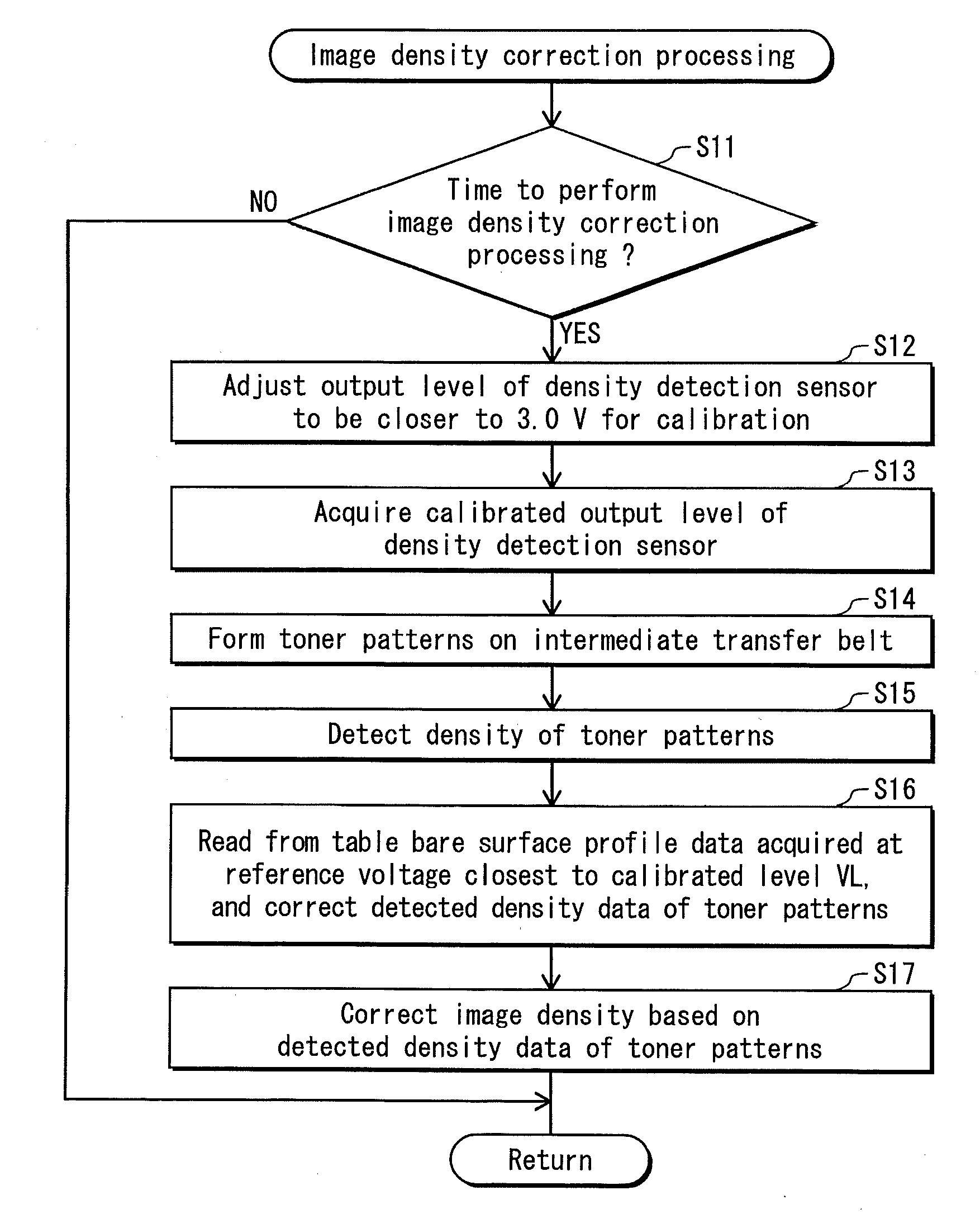
If the shape correction process is omitted, show-through of the manufacturing derived scratches appears on a toner pattern formed in the above image density correction processing, and this deteriorates the detection precision of toner density.
Particularly when detection is performed on a half-tone toner pattern, there occurs markedly such a negative effect caused by the show-through.
This might make it difficult to perform precise image density correction processing.

Method used


Image

  • Image forming apparatus and image density correction method therefor
  • Image forming apparatus and image density correction method therefor
  • Image forming apparatus and image density correction method therefor

Examples


modification examples

[0141]Although the present invention has been described based on the embodiment, the present invention is not limited to the above embodiment. The following modification examples may be employed.

[0142](1) In the above embodiment, detection data of a toner pattern is corrected using bare surface profile data acquired at a reference voltage that is closest to a calibrated level at image density correction processing. Alternatively, it may be possible to estimate bare surface profile data at a reference voltage that matches with the calibrated level at the image density correction processing, based on bare surface profile data that has been already acquired, and correct detection data of a toner pattern based on the estimated bare surface profile data. This can realize more precise performance of image density correction processing.

[0143]In the processing of acquiring bare surface profile data, when bare surface profile data acquired at each reference voltage Vn′ (n=1, 2, 3) is represe...


PUM


Abstract

An image forming apparatus includes: sensor detecting light intensity and output voltage based on the light intensity; data acquisition part setting reference voltages for the sensor to detect light intensity of bare surface of intermediate transfer member, acquiring, at set reference voltage, voltage output by the sensor on the bare surface as detection data; storage storing the detection data corresponding to the reference voltages; judgment part judging whether to perform image density correction processing; voltage calibration part adjusting output level at light intensity detection; density acquisition part forming toner pattern, and acquiring density data of the toner pattern by causing the sensor having adjusted output level to detect its light intensity; density data correction part reading one piece of detection data referring to output level, and correcting the density data based on the detection data; and image density correction part performing the processing based on the density data.

Description

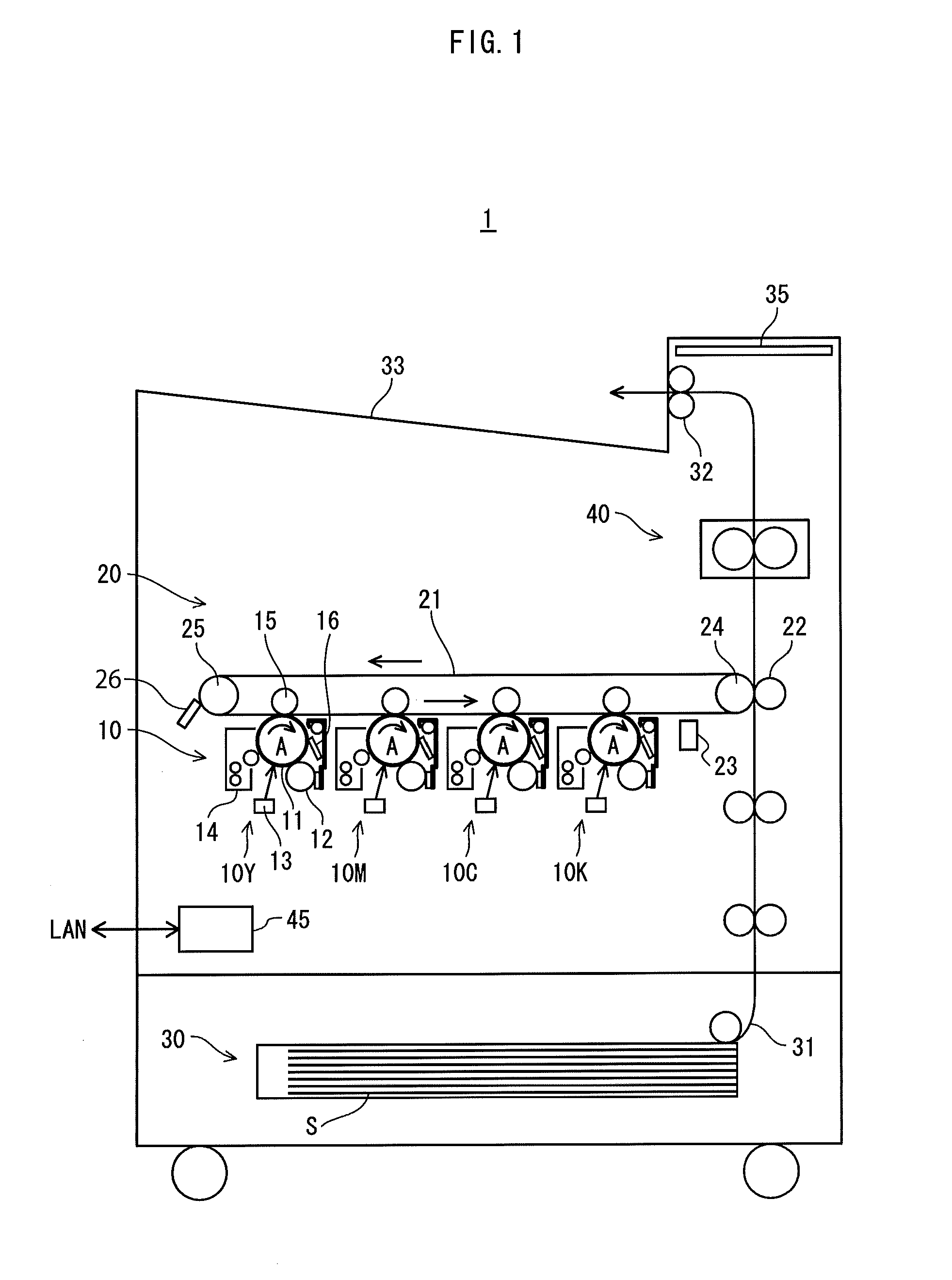
[0001]This application is based on application No. 2010-141323 filed in Japan, the content of which is hereby incorporated by reference.BACKGROUND OF THE INVENTION[0002](1) Field of the Invention[0003]The present invention relates to an image forming apparatus, and particularly to an image density correction technology for correcting density and tint of a reproduced image in the image forming apparatus.[0004](2) Description of the Related Art[0005]An image forming apparatus employing an electrophotographic system has the following structure. A surface of a photosensitive member is uniformly charged by a charger, and the charged surface of the photosensitive member is scanned by laser light to form an electrostatic latent image. Then, toner is supplied to the electrostatic latent image by a developer to develop the electrostatic latent image. A toner image resulting from the above process is primarily transferred onto an intermediate transfer member such as an intermediate transfer b...

Claims


Application Information

Patent Timeline
Patent Type & Authority Applications(United States)
IPC IPC(8): G03G15/16
CPCG03G15/0131G03G2215/00059G03G15/5058G03G15/0194G03G15/162G03G2215/0132
Inventor INADA, YASUYUKIHIRATA, KATSUYUKI
Owner KONICA MINOLTA BUSINESS TECH INC
Learn More