Roof structure having an arrangement of solar panels

a technology of solar panels and roof structures, applied in the direction of solar heat collectors for particular environments, photovoltaics, heat collector mounting/support, etc., can solve the problems of more expensive design than the modules held in normal metal frames, and achieve the effect of avoiding the separation of clamps and associated supporting elements, reducing manufacturing costs, and simplifying installation

Inactive Publication Date: 2011-12-29
ENERGIEBURO AG
View PDF6 Cites 58 Cited by
  • Summary
  • Abstract
  • Description
  • Claims
  • Application Information

AI Technical Summary

Benefits of technology

[0010]With advantage, the retaining device for overlapping or encompassing the frame profile has a clamp made from a profile material or wire, as components of this kind can be manufactured cost-effectively in large quantities.
[0020]The respective lower solar panel is preferably encompassed at its ridge-side end by at least one retaining device which is formed at least partially by the fixing profile. This simplifies installation in that the solar panel can easily be slid into this retaining device from the eaves-side direction.

Problems solved by technology

However, the design according to U.S. Pat. No. 4,336,524 has the disadvantage that the modules must be held in a specially built frame which makes the design more expensive compared with modules held in normal metal frames.

Method used


Image

  • Roof structure having an arrangement of solar panels
  • Roof structure having an arrangement of solar panels
  • Roof structure having an arrangement of solar panels

Examples


Embodiment Construction

[0027]Before describing an exemplary embodiment in more detail, the following terms are defined in order to simplify the notation:

[0028]“Ridge-side” is understood to mean the direction facing the roof ridge, i.e. the upwards direction along the line of fall of the roof.

[0029]“Eaves-side” is understood to mean the direction facing the eaves of the roof, i.e. the downwards direction along the line of fall of the roof.

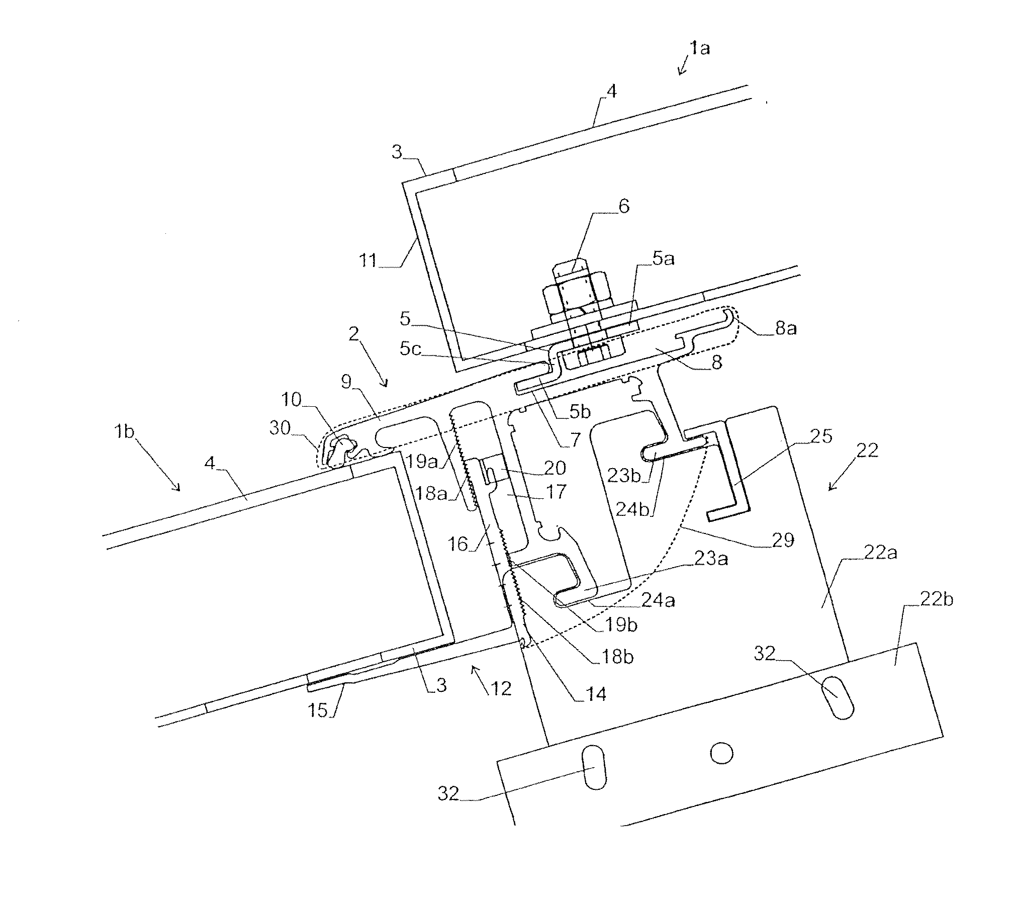
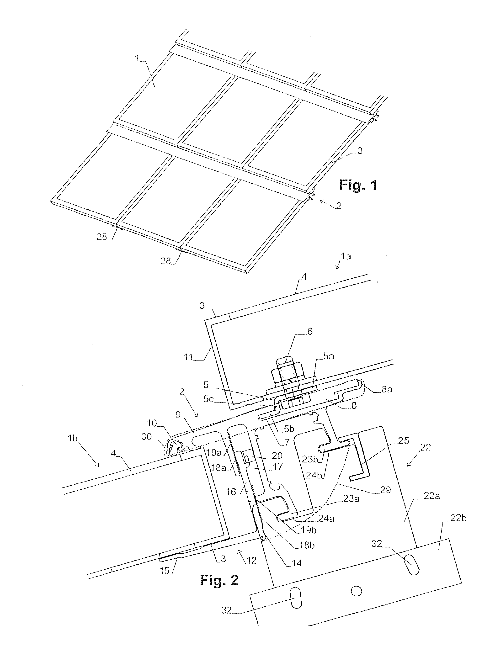
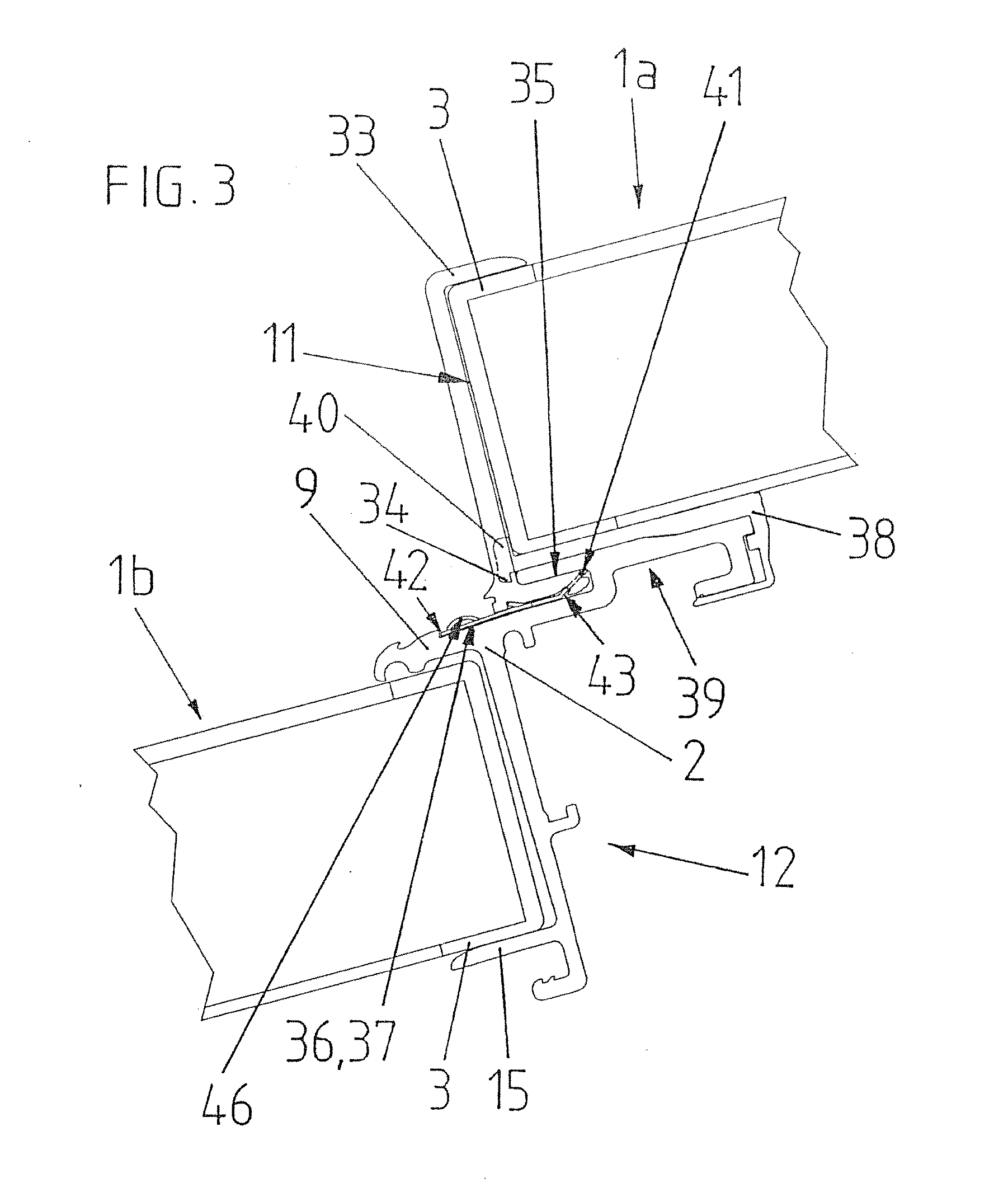
[0030]The arrangement shown in FIG. 1 comprises a plurality of solar modules 1 with fixing profiles 2. The structure of the modules and the fixing profile can be seen in detail from FIG. 2.

[0031]Each solar module 1 has a frame 3 which is made from a metal profile and extends around the module and holds a front plate 4 made from transparent material. Photovoltaic cells (not shown) are arranged inside the module in the usual manner. The solar modules are commercially available models which do not need to be specially adapted for installation in accordance with the invention...


PUM


Abstract

In a roof structure having an arrangement of solar panels, horizontally running fixing profiles are in each case arranged between adjacent solar panels. Each fixing profile extends underneath the frame of the respective upper solar panel and over the frame of the respective lower solar panel and both the upper and the lower solar panel are fixed to the fixing profile. In this way, a laying in a tile-like sealing manner is ensured by the fixing profiles, and at the same time the fixing profiles are used to install the solar panels.

Description

TECHNICAL FIELD[0001]The invention relates to a roof structure having an arrangement of solar panels.[0002]Here, the term “solar panels” is understood to mean plate-like components which are capable of converting solar radiation into other usable forms of energy, in particular electricity or heat. In particular, this includes photovoltaic solar modules (i.e. arrangements of photoelectric solar cells) and solar-thermal collectors (i.e. arrangements which convert solar radiation into heat and heat up a pumped, liquid or gaseous medium of a heating circuit).BACKGROUND ART[0003]Arrangements of the generic kind are used to firmly anchor solar panels in a defined position on a building.[0004]Preferably, such an arrangement should fulfill further functions on the building, for example it should be laid in a tile-like sealing manner and thus be able to undertake the role of conventional tiles. “Laid in a tile-like sealing manner” is understood to mean an arrangement of components in which w...

Claims


Application Information

Patent Timeline
Patent Type & Authority Applications(United States)
IPC IPC(8): E04D13/18H01L31/042
CPCF24J2/5211F24J2/5245F24J2/5254F24J2/5258F24J2002/0061H02S20/23F24J2002/4672Y02B10/12Y02B10/20Y02E10/47F24J2002/4661F24J2002/4665F24S25/61F24S2025/6008F24S25/632F24S25/20F24S2025/6002F24S25/636F24S2020/13F24S2025/6004Y02E10/50Y02B10/10
Inventor MEIER, CHRISTIAN
Owner ENERGIEBURO AG
Why Eureka
Try Eureka