Fuel supply apparatus

a technology of fuel supply and attachment parts, which is applied in the direction of liquid fuel feeders, machines/engines, transportation and packaging, etc., can solve the problems of maintenance problems, manual disengagement of attachment parts,

Active Publication Date: 2011-12-29
HITACHI ASTEMO LTD
View PDF11 Cites 3 Cited by
  • Summary
  • Abstract
  • Description
  • Claims
  • Application Information

AI Technical Summary

Benefits of technology

The present invention has been made in view of the above problems. It is an object of an embodiment of the present invention to provide a fuel supply apparatus with increased maintainability.
Since the three engaging holes are spaced at equal intervals, the engaging holes are well balanced in position, and the lower case and the upper case can be assembled and disassembled easily and efficiently.

Problems solved by technology

Therefore, it would be difficult to manually disengage the attachment member from the engaging hole without any tools, thus posing maintenance problems.

Method used


Image

  • Fuel supply apparatus
  • Fuel supply apparatus
  • Fuel supply apparatus

Examples


Embodiment Construction

A fuel supply apparatus according to an embodiment of the present invention will be described below with reference to the drawings.

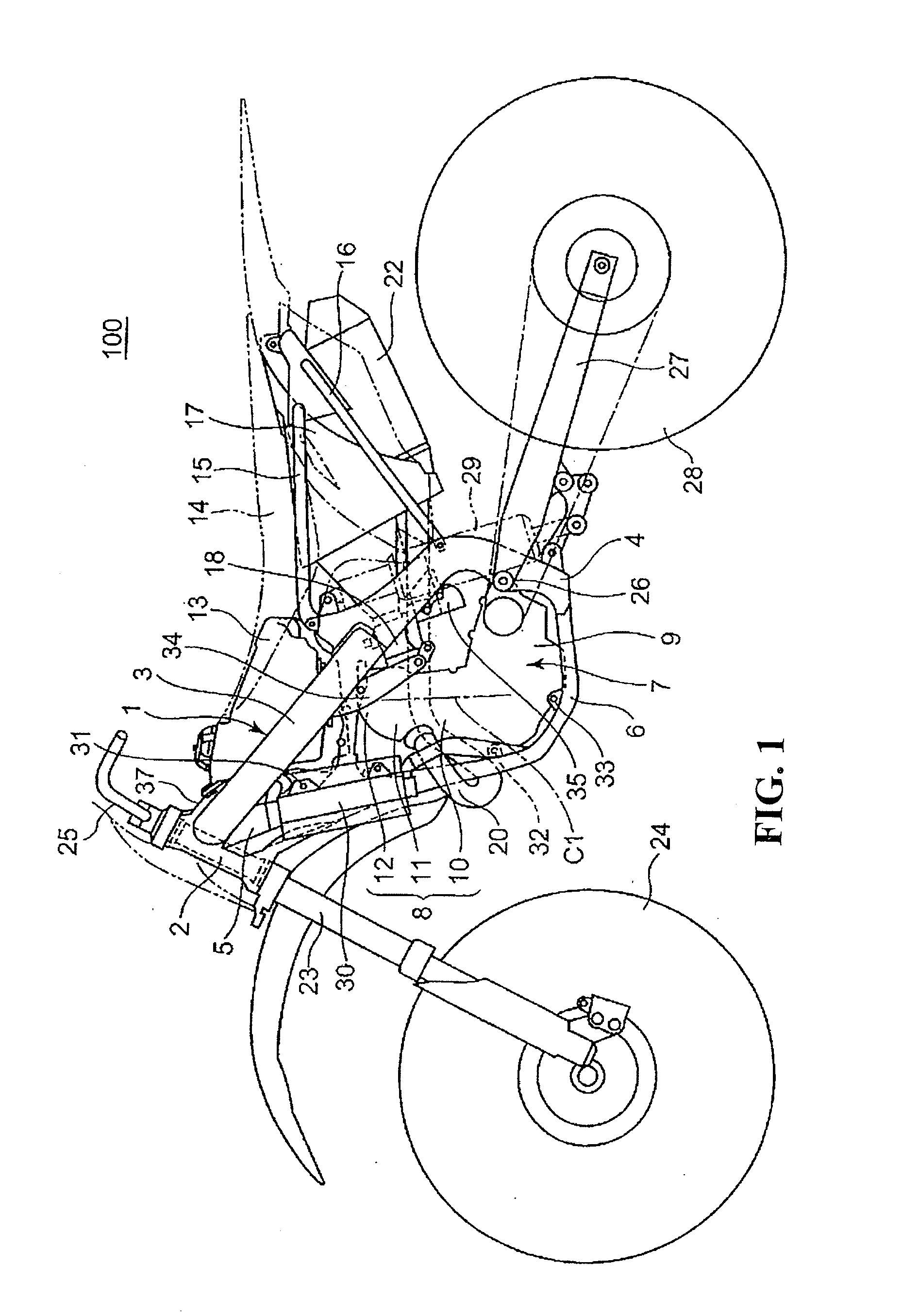
FIG. 1 is a left side elevational view of an off-road motorcycle incorporating a fuel supply apparatus according to an embodiment of the present invention.

A motorcycle 100 including a motorcycle body frame 1 having a head pipe 2, a main frame 3, a central frame 4, a down frame 5, and a lower frame 6 which are joined together into a loop structure with an engine 7 supported therein. The engine 7 includes cylinders 8 and a crankcase 9. Each of the main frame 3, the central frame 4, and the lower frame 6 is provided as a pair of left and right members. Each of the head pipe 2 and the down frame 5 is provided as a single member along the center of the motorcycle body.

The main frame 3 is of a straight shape extending rearwardly downwardly above the engine 7 and joined to an upper end of the central frame 4 which extends vertically behind the engine 7. The dow...


PUM


Abstract

A fuel supply apparatus or fuel pump unit includes a lower case having a flange plate fixed to a fuel tank and upstanding walls extending into the fuel tank. An upper case housing a fuel pump therein is provided that includes brackets disposed along inner sides of the upstanding walls. The upstanding walls having engaging holes defined therein, and the brackets having attachment members engaging in the engaging holes. The brackets include tongues projecting heightwise beyond the upstanding walls.

Description

CROSS-REFERENCE TO RELATED APPLICATIONSThe present application claims priority under 35 USC 119 to Japanese Patent Application No. 2010-148166 filed on Jun. 29, 2010 the entire contents of which are hereby incorporated by reference.BACKGROUND OF THE INVENTION1. Field of the InventionThe present invention relates to a fuel supply apparatus for use with a fuel tank.2. Description of Background ArtHeretofore, a known fuel supply apparatus for use with a fuel tank includes a lower case fixed to the bottom of the fuel tank and an upper case housing a fuel pump and coupled to the lower case. See, for example, Japanese Patent Laid-Open No. 2007-118886. According to Japanese Patent Laid-Open No. 2007-118886, the lower case has a plate-like flange fixed to the fuel tank and an upstanding wall extending into the fuel tank and integral with the plate-like flange. The upper case has a bracket corresponding to the upstanding wall. The upper case is coupled to the lower case by an attachment memb...

Claims


Application Information

Patent Timeline
Patent Type & Authority Applications(United States)
IPC IPC(8): F17D1/00
CPCF02M37/00F02M37/22F02M37/10F02M37/103Y10T137/86035Y10T137/85978
Inventor KOYAMA, SHINYAHOSOYA, KYOHEIKIMURA, KUNIHARAMIYAZAKI, JUNJITSUKAMOTO, HIKARU
Owner HITACHI ASTEMO LTD
Why Eureka
Try Eureka