Inkjet printing apparatus and printing method of inkjet printing apparatus

a technology of inkjet printing and printing method, which is applied in the direction of printing, typewriters, other printing apparatus, etc., can solve the problems of large deviation between the front and rear surface positions of the printed image on the rear surface, large deformation of paper dimensions, and limited accuracy of measuring the amount of deformation of paper, so as to improve the positional deviation

Inactive Publication Date: 2011-12-29
FUJIFILM CORP
View PDF4 Cites 27 Cited by
  • Summary
  • Abstract
  • Description
  • Claims
  • Application Information

AI Technical Summary

Benefits of technology

[0043]According to the present invention, it is possible to improve positional deviation between front and rear surface images, even if there is variation in the type of image formation medium, the ambient storage conditions and the storage time after front surface printing, and the like. Furthermore, since the amount of expansion and contraction of the image formation medium can be measured using an imaging device which is used for ejection failure detection, then this can be achieved by means of a simple composition, without requiring the addition of a dedicated sensor, or the like, for measurement purposes.

Problems solved by technology

On the other hand, with an inkjet printer which uses water-soluble ink, there is a large amount of water contained in the ink, and therefore the paper expands and contracts, depending on the ink volume (image density) adhering to the paper, and the difference between the front and rear surface positions in the printed image on the rear surface (positional deviation between the front and rear images) becomes large, which is a disadvantage compared to the offset printing.
However, in the case of aqueous inkjet printing, there is great deformation of the paper dimensions, depending on the storage time and storage environment after printing on the front surface (first surface), and there has been no simple method for aligning the image positions on the front and rear surface images, which is appropriate in respect of paper deformation of this kind.
Furthermore, in a method which records a reference mark only on a front surface, as proposed in the related art, the accuracy of measurement of the amount of deformation of the paper is limited by the resolution of the imaging system which determines the amount of deformation.

Method used


Image

  • Inkjet printing apparatus and printing method of inkjet printing apparatus
  • Inkjet printing apparatus and printing method of inkjet printing apparatus
  • Inkjet printing apparatus and printing method of inkjet printing apparatus

Examples


first embodiment

Printing Method

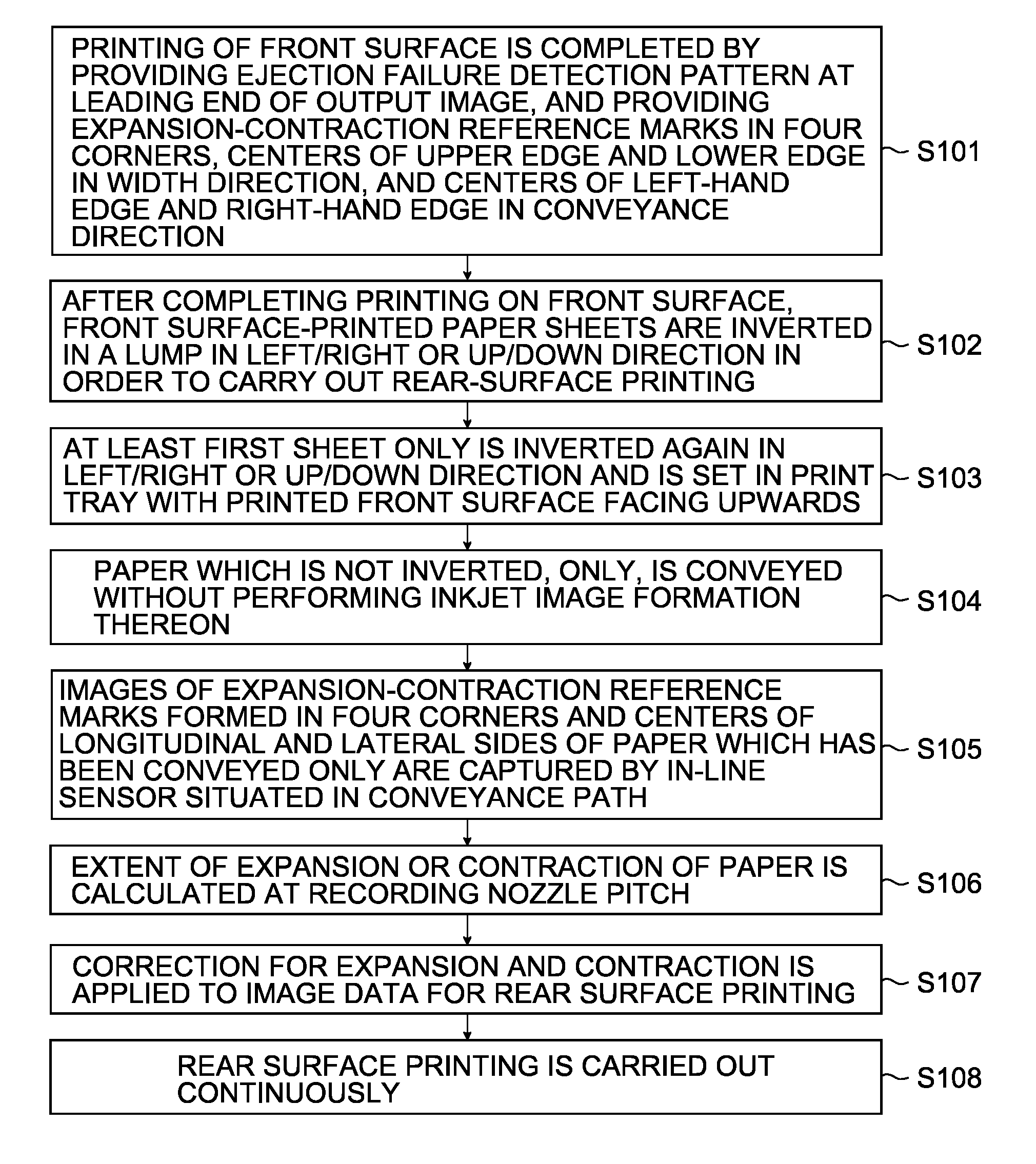
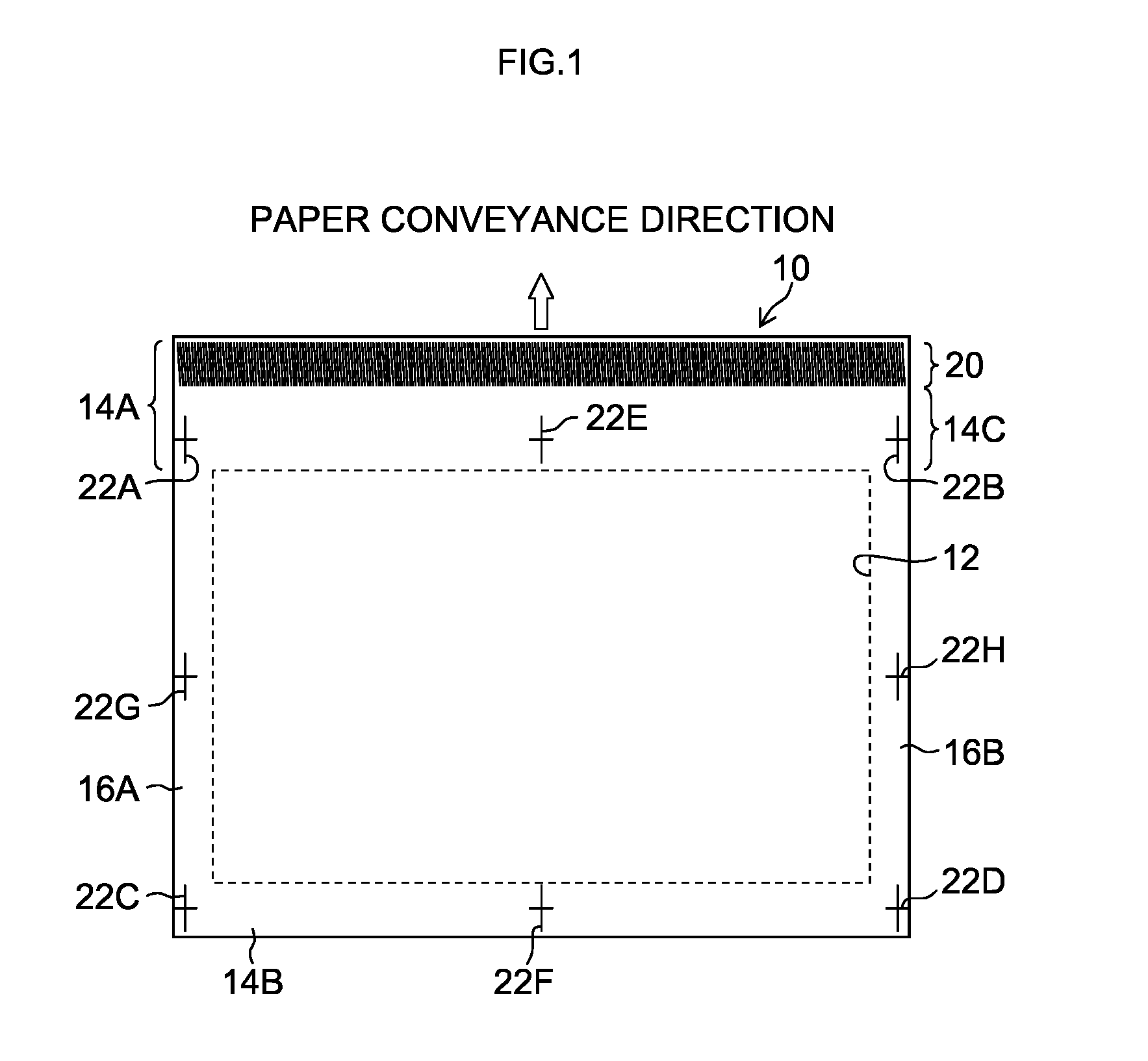
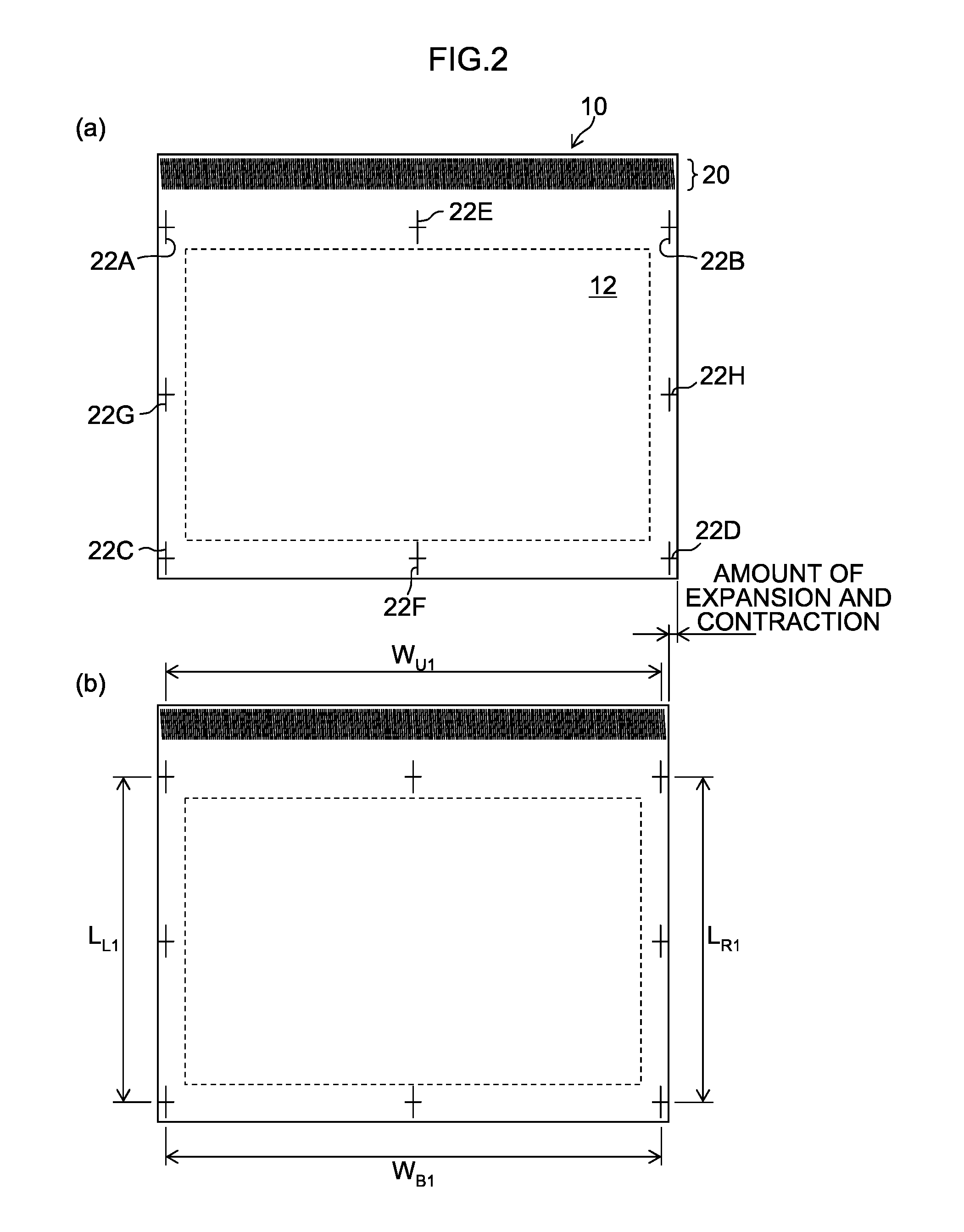
[0076]As stated previously, by passing a set number of sheets of paper of which the printing has been carried out on the front surface only, along the printing conveyance path, and moving the paper directly below the in-line sensor, an image of the ejection failure detection pattern 20 (see FIG. 4) and the expansion-contraction reference marks 22 that have been used when printing is performed on the front surface are captured by the in-line sensor. By this means, it is possible to identify the positions of the expansion-contraction reference marks, at the resolution of the in-line sensor, and the amount of expansion and contraction can be measured.

[0077]More specifically, when outputting a front surface image, an image of the expansion-contraction reference marks 22 provided at the four corners of the image forming region 12 and between the four corners of the image forming region 12 in a central position in the width direction (left / right direction) and in a central ...

second embodiment

Printing Method

[0101]There follows a description of an example of a printing method which employs a method of improving the reading accuracy of expansion-contraction reference marks by using an ejection failure detection pattern that has been recorded during front surface printing.

[0102]The steps of printing on the front surface, obtaining a stack of sheets of front surface-printed paper, gathering the paper stack together and inverting the front / rear surfaces in a lump sum are the same as in the first embodiment. Thereupon, when rear surface printing is to be performed (and desirably, immediately before rear surface printing), a prescribed number of sheets including at least the first one sheet of the stack of front surface-printed paper are inverted in the up / down or left / right direction and set in the paper supply unit (print tray) with the printed front surface facing upwards, and a new expansion-contraction reference pattern is recorded additionally on the front surface. In thi...

modification examples

[0214]In the embodiments described above, an inkjet printing apparatus based on a method which forms an image by ejecting ink droplets directly onto the recording medium (direct recording method) is described, but the application of the present invention is not limited to this, and the present invention can also be applied to an image forming apparatus of an intermediate transfer type which provisionally forms an image (primary image) on an intermediate transfer body, and then performs final image formation by transferring the image onto recording paper in a transfer unit.

[0215]Furthermore, in the embodiments described above, an inkjet printing apparatus using a page-wide full-line type head having a nozzle row of a length corresponding to the full width of the recording medium (a single-pass image forming apparatus which completes an image by a single sub-scanning action) is described, but the application of the present invention is not limited to this and the present invention can...


PUM


Abstract

An inkjet printing apparatus includes: an inkjet head having nozzles which eject ink; a first conveyance device which moves at least one of an image formation medium and the inkjet head during image formation by the inkjet head; a second conveyance device which conveys the image formation medium along a conveyance path after the image formation by the inkjet head; an imaging device; a test pattern printing control device which controls ejection of the inkjet head; an ejection failure nozzle detection processing device; an expansion-contraction reference mark printing control device; an expansion-contraction deformation amount measurement device; an image deformation processing device which applies image deformation processing corresponding to the amount of deformation due to expansion and contraction, to image data to be printed on the second surface,; and a print control device which carries out the printing on the second surface on a basis of the image data which has been corrected through the image deformation processing.

Description

BACKGROUND OF THE INVENTION[0001]1. Field of the Invention[0002]The present invention relates to an inkjet printing apparatus, and more particularly to technology for improving positional deviation between front and rear surface images produced by double-side printing.[0003]2. Description of the Related Art[0004]When performing double-side printing by an offset printing machine using a printing plate, normally, after printing on a front surface with trim marks, the paper is inverted and the rear surface printing is carried out, whereupon an operator looks through the resulting output printed object, or performs an inspection by passing a needle therethrough, and the tension of printing plate is adjusted, and the like, on the basis of the inspection results, so as to align the positions of the rear and front surfaces. In the case of an offset printer, since there is a small amount of water in the ink compared to aqueous inkjet printing, then there has been virtually no problem of def...

Claims


Application Information

Patent Timeline
Patent Type & Authority Applications(United States)
IPC IPC(8): B41J29/393
CPCB41J3/60B41J2/2142
Inventor SAITA, HIROFUMI
Owner FUJIFILM CORP
Why Eureka
Try Eureka