Control device for machine tool including rotary indexing device

a control device and machine tool technology, applied in computer control, program control, instruments, etc., can solve the problems of increasing machine error, increasing machining load, increasing position deviation, etc., and achieves the effect of swiftly resolving the position deviation of the rotary tabl

Active Publication Date: 2016-12-27
FANUC LTD
View PDF30 Cites 0 Cited by
  • Summary
  • Abstract
  • Description
  • Claims
  • Application Information

AI Technical Summary

Benefits of technology

[0012]Hence, the present invention provides a control device for a machine tool capable of preventing a drive motor which drives a rotary table from being brought into an excessive load state and from becoming overheated, capable of preventing the machine from stopping, and capable of swiftly resolving position deviation of the rotary table which is caused by increase in an instantaneously applied machining load.
[0014]According to this, if the rotary table tries to rotate by a machining load generated when a work mounted on and fixed to the rotary table is machined, output torque of the drive motor which drives the rotary table is not reduced until time during which the output torque is less than upper limit torque and exceeds permissible torque reaches predetermined time, the output torque is continuously output and a rotation position is held. Therefore, machining precision is not lowered with respect to increase in a machining load for a short time.
[0015]If a state where the output torque exceeds the permissible torque continues for predetermined time or if the output torque reaches the upper limit torque, the target position is changed by increments such that output torque of the drive motor becomes close to or equal to 0 until the output torque becomes smaller than the permissible torque. Therefore, it is possible to prevent the excessive load state and overheating of the drive motor, and to prevent the machine from stopping. Therefore, it is possible to enhance an operation rate of the machine. If the target position is changed such that the output torque of the drive motor becomes close to or equal to 0, this change in the target position increases position deviation, and machine error is increased. However, the machining load is normally increased for a very short time, and the position is held for the predetermined time during which output torque is less than the upper limit torque and exceeds the permissible torque. Therefore, time during which the output torque is changed such that the output torque becomes close to or equal to 0 is short, and a period during which machine error becomes large is normally extremely short.
[0016]It is possible to employ such a configuration that when a target position is changed by the target position changing unit, target position-change signal output unit turns ON a target position-change signal indicating that the target position is changed and the target position-change signal output unit outputs this target position-change signal, and when the target position returning unit returns the target position to the original target position when the rotary table is clamped, the target position-change signal output unit turns the target position-change signal OFF. According to this, a machined section where the target position is changed can be detected. It is possible to know that a work is machined in a state where the rotary table is deviated in position by an ON signal of the target position-change signal which indicates that the target position is changed. Therefore, it is possible to know a machining region having a possibility that machining precision is deteriorated.
[0017]It is possible to employ such a configuration that the clamping mechanism clamps the rotary table at a target position of a predetermined rotation angle position, and the control device further includes clamping-time position deviation signal output unit which outputs a clamping-time position deviation signal if output torque detected by the drive motor output torque detecting unit becomes equal to or higher than a predetermined value before a machining operation is started. According to this, when the rotary table is clamped by the clamping mechanism, the rotary table is clamped in a state where the rotary table rotates and a position thereof is deviated due to a clamping error or the drive motor is positioned within the in-position width. However, it is possible to discover that the rotary table is clamped in a state where large position deviation within the in-position width remains. It is possible to detect that a clamping error in which the rotary table is rotated and clamped when the rotary table is clamped by the clamping mechanism is generated, and it is possible to prevent a useless machining operation caused by clamping error.

Problems solved by technology

If the target position is changed such that the output torque of the drive motor becomes close to or equal to 0, this change in the target position increases position deviation, and machine error is increased.
However, the machining load is normally increased for a very short time, and the position is held for the predetermined time during which output torque is less than the upper limit torque and exceeds the permissible torque.
Therefore, time during which the output torque is changed such that the output torque becomes close to or equal to 0 is short, and a period during which machine error becomes large is normally extremely short.

Method used


Image

  • Control device for machine tool including rotary indexing device
  • Control device for machine tool including rotary indexing device
  • Control device for machine tool including rotary indexing device

Examples


Embodiment Construction

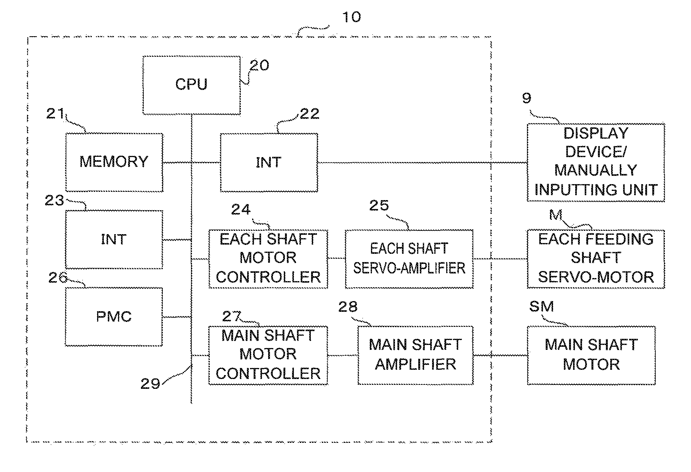
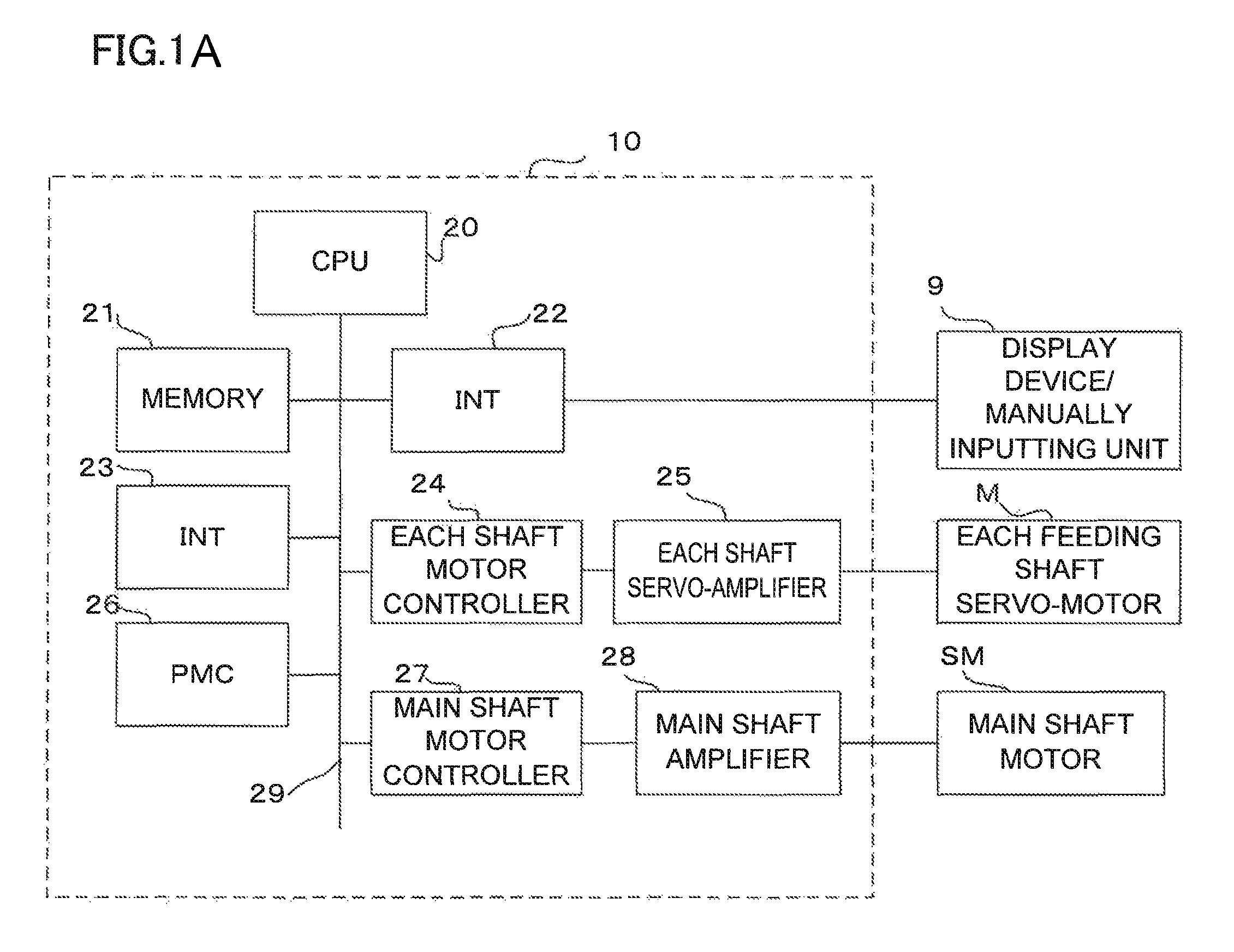
[0026]FIG. 1A is a block diagram of a controller which drives and controls a machine tool according to an embodiment.

[0027]A reference sign 10 represents a numeric value control device as a control device which controls a machine tool. A CPU 20 is a processor which totally controls the numeric value control device 10, and the CPU 20 is connected to a memory 21, interfaces 22 and 23, an each shaft motor controller 24, a PMC (programmable machine controller) 26 and a main shaft motor controller 27 through buses 29. The CPU 20 retrieves a system program stored in a ROM in the memory 21 through the bus 29, and controls the entire numeric value control device 10 in accordance with the system program. The memory 21 includes the ROM, a RAM and a nonvolatile memory. The system program is stored in the ROM. Temporary calculation data, display data and various data which is input through a display device / manually inputting unit 9 are stored in the RAM. The nonvolatile memory is composed of a ...


PUM


Abstract

A rotary table is rotated by a machining load. A drive motor tries to return the rotary table to a positioned target position, and increases output torque. When the output torque reaches upper limit torque Tmax or when output torque which is equal to or greater than permissible torque Tp continues for predetermined time ΔT, a target position which is sent to a drive motor is changed, thereby promoting reduction in output torque. If the output torque becomes smaller than permissible torque Tp, the target position is changed to bring position deviation of the drive motor equal to 0, and the position deviation is swiftly returned.

Description

RELATED APPLICATIONS[0001]The present application claims priority to Japanese Application Number 2013-223591, filed Oct. 28, 2013, the disclosure of which is hereby incorporated by reference herein in its entirety.BACKGROUND OF THE INVENTION[0002]1. Field of the Invention[0003]The present invention relates to a control device for a machine tool. More specifically, the invention relates to a control device for a machine tool including a rotary indexing device composed of a rotary table on which a work is mounted, a clamping mechanism for holding an angular position of the rotary table, and a drive motor for driving the rotary table.[0004]2. Description of the Related Art[0005]In a machine tool including a rotary indexing device composed of a rotary table, a clamping mechanism for holding the rotary table, and a drive motor for driving the rotary table, a work is mounted on and fixed to the rotary table, the rotary table is rotated by the drive motor to position the rotary table to a ...

Claims


Application Information

Patent Timeline
Patent Type & Authority Patents(United States)
IPC IPC(8): B23Q1/64B23Q3/08G05B19/402B23Q16/06
CPCB23Q3/08G05B19/402B23Q16/065G05B2219/39264G05B19/406
Inventor OGAWA, YOSHITSUGU
Owner FANUC LTD
Why Eureka
Try Eureka