Broaching Stability Monitoring Method and System

A technology of stability and stability map, applied in metal processing equipment, metal processing mechanical parts, broaching machines, etc., can solve the problem of relative position deviation between the tool and the workpiece, and achieve the effect of solving the relative position deviation

Active Publication Date: 2021-06-22
CENT SOUTH UNIV
View PDF0 Cites 0 Cited by
  • Summary
  • Abstract
  • Description
  • Claims
  • Application Information

AI Technical Summary

Problems solved by technology

[0004] The invention provides a broaching stability monitoring method and system to solve the technical problem of the relative position deviation between the tool and the workpiece caused by the vibration of the existing system

Method used


Image

  • Broaching Stability Monitoring Method and System
  • Broaching Stability Monitoring Method and System
  • Broaching Stability Monitoring Method and System

Examples


Embodiment 1

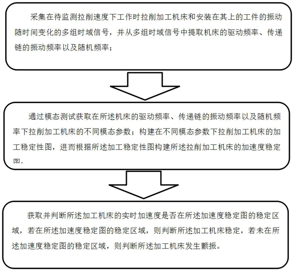
[0038] Such as figure 1 As shown, the invention discloses a method for monitoring the stability of broaching, comprising the following steps:

[0039] Collect multiple sets of time-domain signals of the vibration of the broaching machine tool and the workpiece installed on it when working at the broaching speed to be monitored, and extract the drive frequency of the machine tool and the transmission chain from the multiple sets of time-domain signals. vibration frequency and random frequency;

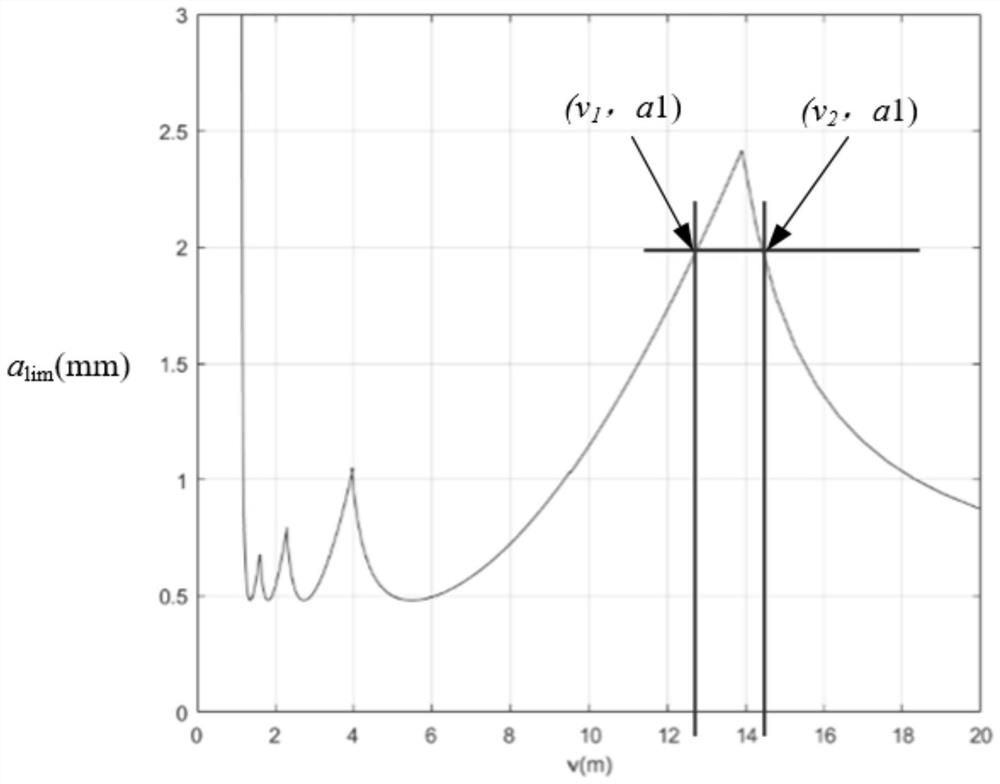
[0040] Through the modal test, the different modal parameters of the broaching machine tool when working at the drive frequency of the machine tool, the vibration frequency of the transmission chain and the random frequency are obtained; the processing stability diagram of the broaching machine tool is constructed under different modal parameters, Then constructing an acceleration stability diagram of the broaching machine tool according to the processing stability diagram;
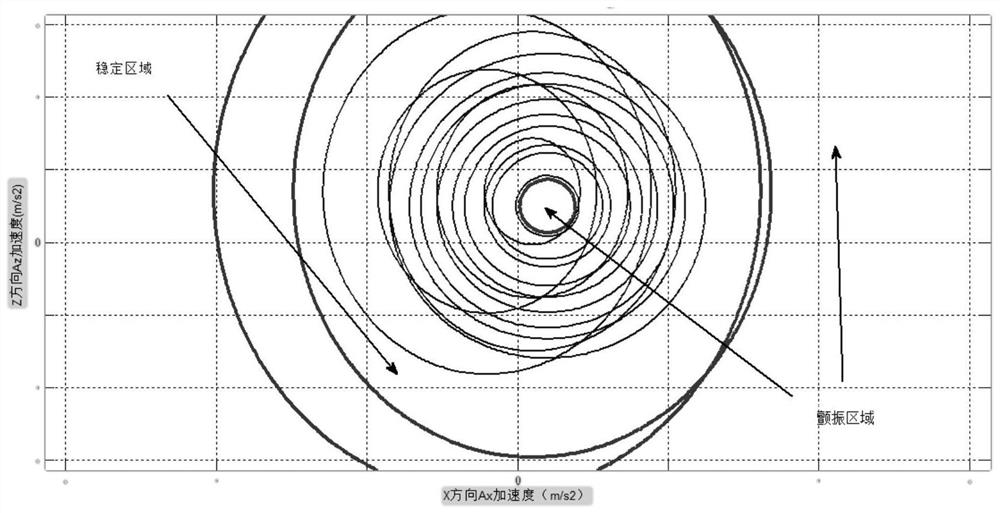
[0041] A...

Embodiment 2

[0045]Embodiment 2 is a preferred embodiment of Embodiment 1. It differs from Embodiment 1 in that the specific steps of the broaching stability monitoring method are refined and optimized, specifically including the following:

[0046] Machine tools are ubiquitous and difficult to avoid vibration, which mainly includes the vibration generated by the idling of the machine tool and the vibration during the cutting process. Among the above vibrations, there are free vibration, forced vibration, self-excited vibration and mixed vibration. Since the vibration of various structures in precision broaching affects the precision of processing, and the vibration of its structure corresponds to its dynamic characteristics, in order to solve this problem, the broaching stability monitoring method and system provided in this embodiment, Obtain the vibration frequency of the vibration source and the corresponding modal parameters (modal stiffness, modal mass) through the modal test, and es...


PUM


Abstract

The invention discloses a broaching stability monitoring method and system. By collecting multiple sets of time-domain signals of the vibration of the machine tool and the workpiece changing with time when the broaching machine tool is working at the broaching speed to be monitored, the multiple sets of time-domain signals are obtained. Extract the driving frequency of the machine tool, the vibration frequency of the transmission chain and the random frequency, and obtain the different modal parameters of the cutting machine tool under the driving frequency, the vibration frequency of the transmission chain and the random frequency through the modal test; The acceleration stability diagram of the machining machine tool; judge whether the real-time acceleration of the processing machine tool is in the stable area of ​​the acceleration stability diagram, if it is in the stable area of ​​the acceleration stability diagram, then it is judged that the processing machine tool is stable; if it does not fall in the stable area of ​​the acceleration stability diagram, then Judging that the processing machine tool will vibrate, and then effectively monitor the stability of the processing machine tool, discover the chatter phenomenon of the processing machine tool in time, and solve the problem of relative position deviation between the tool and the workpiece caused by the vibration of the existing system.

Description

technical field [0001] The invention relates to the field of broaching, in particular to a method and system for monitoring the stability of broaching. Background technique [0002] During the broaching process, different types of vibration of the broaching machine will cause deviations in the relative position of the tool and the workpiece, the position and time of the kinematic chain transmission, and different types of vibration have different effects on the machining accuracy, especially when used for connection In the machining of the tongue and groove of the complex and high-precision requirements of the turbine disk blade. The existing methods for improving the machining accuracy of broaching mainly focus on the identification of the relative error between the tool and the workpiece, and use different strategies for motion compensation to improve the machining accuracy. It is difficult to accurately obtain the relative position of the tool and the workpiece caused by ...

Claims


Application Information

Patent Timeline
Patent Type & Authority Patents(China)
IPC IPC(8): B23Q17/00B23D39/00
CPCB23D39/00B23Q17/00
Inventor 唐进元陈雪林
Owner CENT SOUTH UNIV
Why Eureka
Try Eureka