

Hand-operated hydraulic press with drilling jig
A technology of drilling jig and hydraulic press, which is applied in the direction of clamping, manufacturing tools, metal processing equipment, etc., can solve the problems of frequent wear and uncontrollable balanced tightening, etc., achieve the effects of firm fixation, solution of positional deviation, and improvement of work efficiency
Inactive Publication Date: 2013-11-20
刘恩宏
View PDF5 Cites 0 Cited by
- Summary
- Abstract
- Description
- Claims
- Application Information
AI Technical Summary
Problems solved by technology
However, it is impossible to control the balanced tightening by the feeling of the hand. Moreover, these screws have to be tightened and loosened every time a workpiece is processed, causing frequent wear and tear.
Method used
View moreImage
Smart ImageViewing Examples

Examples
Embodiment Construction
Login to View More PUM
 Abstract
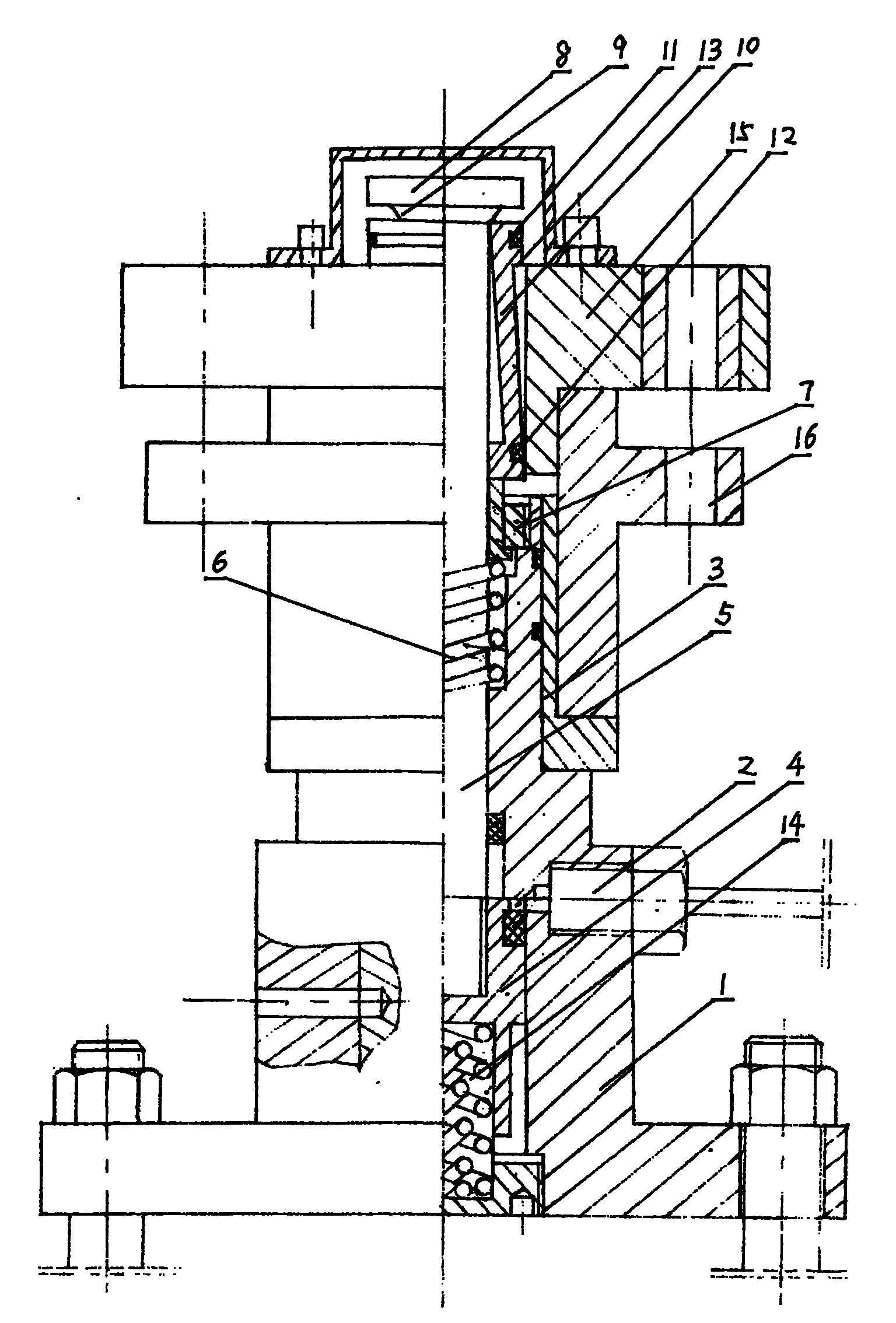
The invention relates to a hand-operated hydraulic press with a drilling jig, belonging to the technical field of machine manufacturing. The hand-operated hydraulic press with a drilling jig is composed of a base, a hydraulic device, a shaft cavity, a draw rod, a return spring, a differential spring, a spacing seat, a gland, a buckling block, an upper tightening loop, a lower tightening loop and a drilling jig, wherein the shaft cavity is fixed on the base; the lower part of the draw rod is arranged in the shaft cavity; the bottom of the draw rod is connected with a piston of the hydraulic device; the top end of the draw rod is fixedly connected with the gland through a conical neck; the draw rod is provided with the buckling block; the top of the shaft cavity is provided with the spacing seat; and the upper surface of the drilling jig is corresponding to the position of the clamping platform of the buckling block. The hand-operated hydraulic press with a drilling jig is operated in the following way: a workpiece is sheathed in the shaft cavity, the drilling jig is pressed on the workpiece, the draw rod moves downward, and the clamping platform of the buckling block drives the drilling jig to compress the workpiece, thereby clamping the workpiece. The invention can accurately position the processed workpiece, and solves the problem of true position deviation.
Description
technical field [0001] The invention belongs to the technical field of mechanical manufacturing, and relates to a clamp. Background technique [0002] At present, the commonly used machine-added drilling jigs are fixed with screw pressure bridge plates, fixed with screw gland plates, and also fixed with tapered iron pin grooves, and fixed with drill mold glands with double lug reverse buckle tension and pressure belt positioning holes, etc. These toolings have cumbersome and time-consuming operating procedures. It is difficult to achieve quantitative production of programmed and large-scale drilling workpieces. The positioning deviation is too large. At the same time, the tooling parts are easy to wear, and the workpiece is unbalanced and directly Affects the position of drilling and other issues. [0003] For example, for tooling with double-hanging lugs, buckle, pull and press with positioning holes, the table top should be cleaned first for each workpiece to be processed...
Claims
Login to View More Application Information
Patent Timeline
 Patent Type & AuthorityPatents(China)
IPC IPC(8): B23Q3/06B23B47/28
Inventor刘恩宏刘国方
Owner刘恩宏