Apparatus and method of depth coding using prediction mode

a technology of depth image and coding apparatus, which is applied in the direction of signal generator with optical-mechanical scanning, color television with bandwidth reduction, and color television with inconsistent multi-view color images. it can solve the problems of linear increase or decrease of the value of the object that moves, the frequency of errors in the prediction of images based on time, and the inability to predict the imag

Inactive Publication Date: 2011-12-29
SAMSUNG ELECTRONICS CO LTD +1
View PDF17 Cites 191 Cited by
  • Summary
  • Abstract
  • Description
  • Claims
  • Application Information

AI Technical Summary

Benefits of technology

The foregoing and/or other aspects are achieved by providing a method, including generating, by at least one processor, a prediction mode to encode a multi-view image based on temporal correlation of images of an object, the generating including calculating a first depth representative value of a current block of a depth image and a second depth representative value of a reference block of the depth

Problems solved by technology

The multi-view color image may be inconsistent between images even though careful attention is paid to an image obtaining process.
The most frequent inconsistency is an illumination inconsistency between color images photograph

Method used


Image

  • Apparatus and method of depth coding using prediction mode
  • Apparatus and method of depth coding using prediction mode
  • Apparatus and method of depth coding using prediction mode

Examples


Embodiment Construction

Reference will now be made in detail to embodiments, examples of which are illustrated in the accompanying drawings, wherein like reference numerals refer to the like elements throughout. Embodiments are described below to explain the present disclosure by referring to the figures.

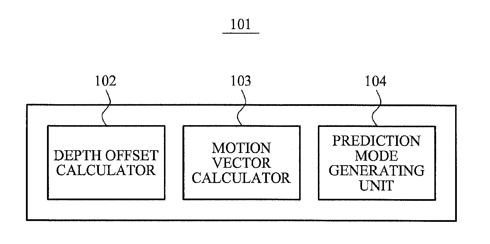
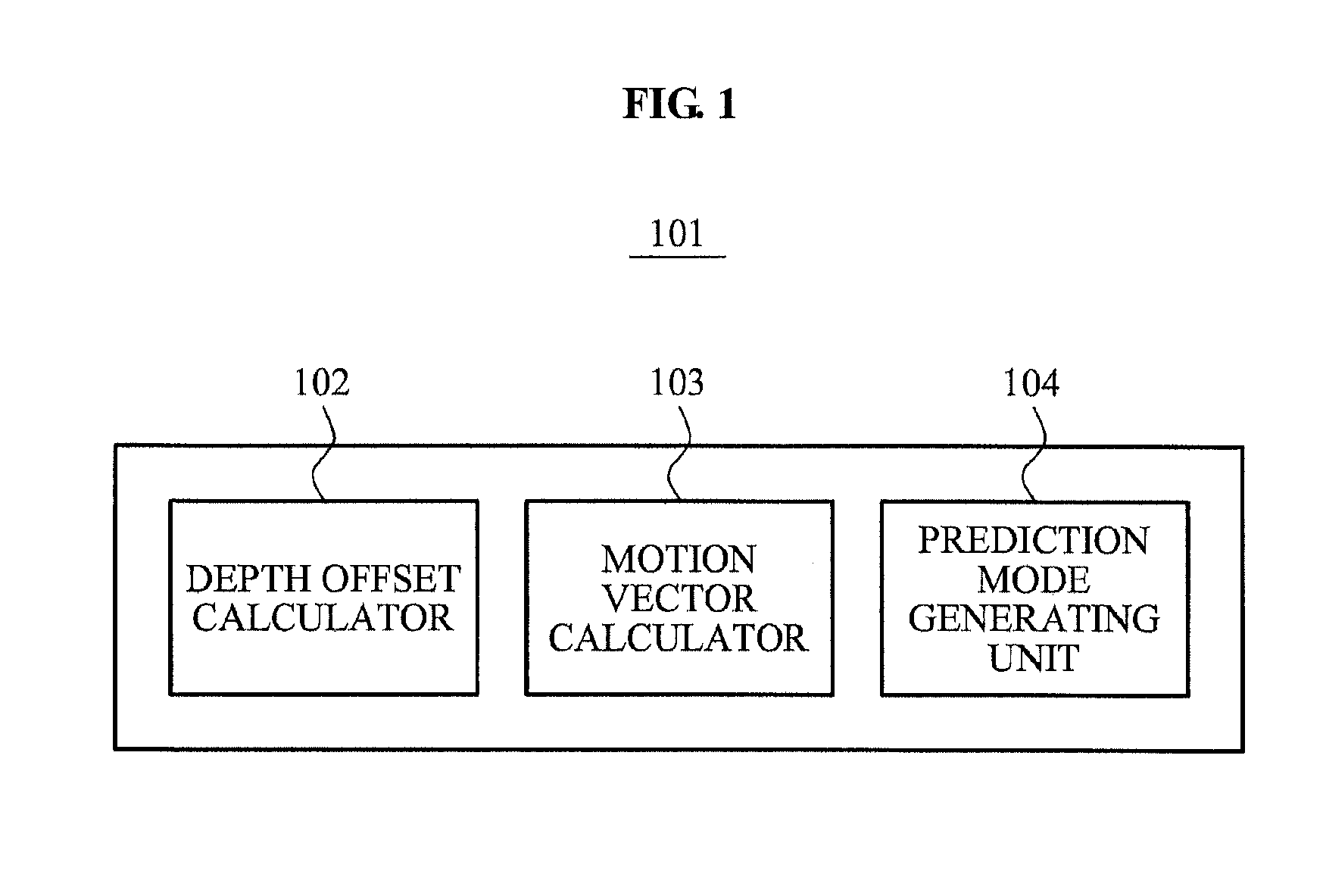
FIG. 1 illustrates an example of a prediction mode generating apparatus.

Referring to FIG. 1, a prediction mode generating apparatus 101 that generates a prediction mode having a compensated depth value may include a depth offset calculator 102, a motion vector calculator 103, and a prediction mode generating unit 104.

A depth image may be an image where information associated with a depth, i.e., a distance, between an object in a three-dimensional (3D) video and a camera is expressed as a two-dimensional (2D) video format.

According to example embodiments, depth information of the depth image may be transformed to a depth value based on Equation 1.

Z=Zfar+v·Znear-Zfar255withv∈[0,…,255][Equation1]

In Equation 1...


PUM


Abstract

A depth image coding method may calculate a depth offset of a depth image, may generate a prediction mode based on the depth offset, may minimize a prediction error of the depth image having a low correlation between adjacent points of view and a low temporal correlation and may enhance a compression rate. The depth offset may be calculated based on a representative value of adjacent pixels included in a template as opposed to using a depth representative value of pixels in a block and header information may not be needed to encode an offset and the offset may be generated by a depth image decoding apparatus. When a plurality of objects is included in a block, a depth offset is calculated for each of the plurality of objects and a motion vector is calculated for each of the plurality of objects and the depth image may be accurately predicted.

Description

CROSS-REFERENCE TO RELATED APPLICATIONSThis application claims the priority benefit of Korean Patent Application No. 10-2010-0060798, filed on Jun. 25, 2010, in the Korean Intellectual Property Office, the disclosure of which is incorporated herein by reference.BACKGROUND1. FieldExample embodiments relate to a depth image coding apparatus and method using a prediction mode and a prediction mode generating apparatus and method, and more particularly, to a depth image coding apparatus and method using a prediction mode and a prediction mode generating apparatus and method that may generate the prediction mode.2. Description of the Related ArtRecently, a three-dimensional (3D) video system includes depth data and a color image of at least two points of view. Accordingly, the 3D video system may need to effectively encode a quantity of input data and may need to perform coding both a multi-view color image and a multi-view depth image corresponding to the multi-view color image.The mult...

Claims


Application Information

Patent Timeline
IPC IPC(8): H04N7/32H04N7/50
CPCH04N19/597H04N19/105H04N19/20H04N19/17H04N19/137
Inventor LIM, IL SOONHO, YO SUNGLEE, JAE JOONKANG, MIN KOO
Owner SAMSUNG ELECTRONICS CO LTD
Why Eureka
Try Eureka