Transportation method for wind energy converters at sea

a technology transport methods, which is applied in the direction of underwater structures, floating buildings, artificial islands, etc., can solve the problems of large special ships and expensive cranes that have to carry the entire weight of wind energy converters

Inactive Publication Date: 2011-12-29
THEY JAN ALEXIS
View PDF5 Cites 3 Cited by
  • Summary
  • Abstract
  • Description
  • Claims
  • Application Information

AI Technical Summary

Benefits of technology

[0024]It is advantageous, if the hinged pillar produce the exes buoyancy responsible for the dynamic behavior of the buoyancy supported device. This way it is shore, that the joint between carrying unit and connecting elements is not loaded by the exes buoyancy.
[0025]Buoyancy supported foundation where a

Problems solved by technology

A disadvantage of this method is, that the crane has to carry the entire weight of the wind en

Method used


Image

  • Transportation method for wind energy converters at sea
  • Transportation method for wind energy converters at sea
  • Transportation method for wind energy converters at sea

Examples


Embodiment Construction

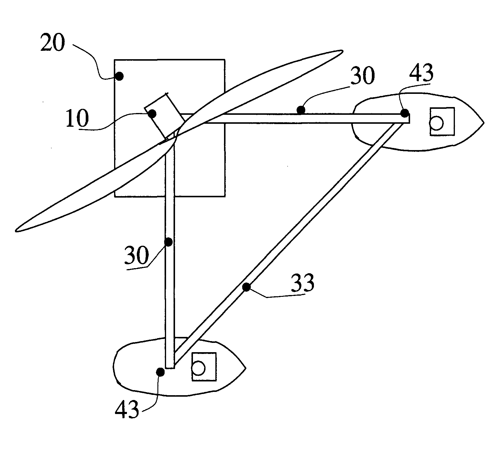
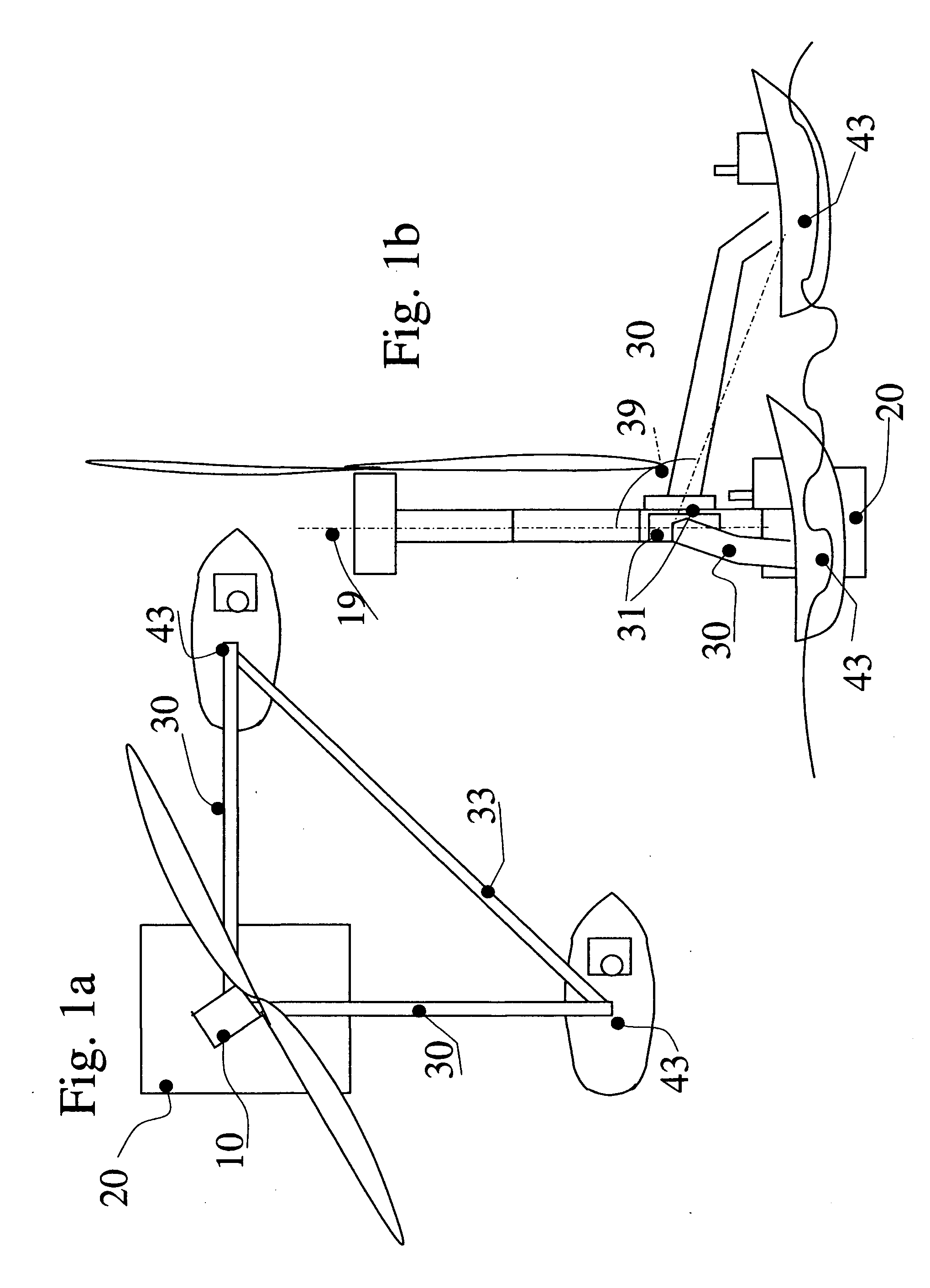
[0034]FIG. 1: The wind energy converter (10) is situated on the buoyant body (20), shown schematically, that is carrying at least partially the load of the buoyant body. The device is supported via the outriggers (30) on the assisting ships (40). The mounting element (31), that is used to mount the outrigger to the offshore construction can be moved in a controlled way, so that the angel between the vertical axes (11) can be adjusted in a controlled way.

[0035]On the assisting ships (40) the outriggers are attached vial pivot joints (43), that allow the outriggers to be pivoted into all directions. Fertile this pivot joint (43) is mounted close to the design location of the center of mass of the ship, because this way the response of the ship to the motion of the sea does hardly change. By it own drive an the rudder the direction of the ship can be controlled. By the ships acting together the device can be moved into every direction, and it also can be turned around its vertical axes...


PUM


Abstract

A method and device for installing wind energy converters at sea is disclosed, whereby the wind energy converter is carried by a setup of buoyant bodies, characterized in that the wind energy converter is connected to ships by outriggers, in a way that allows to give the angle between outrigger and the vertical axis, in order to control the orientation of swimming.

Description

CLAIM FOR PRIORITY[0001]This application claims priority to German application number DE 10 2010 0260242.0, which was filed in the German language on Jun. 27,2010 and which is hereby incorporated by reference.BACKGROUND OF THE [0002]The invention relates to a method and a device for the building, the transport and the installation of offshore construction, especially wind energy converters.BACKGROUND OF THE INVENTION[0003]Especially wind energy converters are characterized in that the center of mass is situated high, and the wind load is large. Fore foundations of wind energy converters that utilize buoyancy, the stability is established by the anchoring, instead of the freeboard or location of weight, because ballast or freeboard would have to be much lager than for compensating the forces of mass alone.[0004]As during the transport it is not possible to establish stability of the offshore construction by anchoring, in the following, a method is suggested, that makes the stabilizat...

Claims


Application Information

Patent Timeline
IPC IPC(8): E02B17/00B63B35/44
CPCF03D1/001F03D1/005Y02E10/727F05B2230/6102F05B2240/95F03D11/04F03D13/25F03D13/10F03D13/40B63B35/003Y02P70/50Y02E10/72
Inventor THEY, JAN ALEXIS
Owner THEY JAN ALEXIS
Why Eureka
Try Eureka