Device for mixing at least two gaseous components

a technology of gaseous components and mixers, applied in the direction of mixers, lift valves, functional valve types, etc., can solve the problems of high cost of mixer types, inability to achieve the effect of mixing, and inability to implement substantial means, so as to reduce the connection

Inactive Publication Date: 2012-01-05
AKHEA
View PDF10 Cites 22 Cited by
  • Summary
  • Abstract
  • Description
  • Claims
  • Application Information

AI Technical Summary

Benefits of technology

[0007]The objectives of this invention are to realize devices for mixing that are modular and compact, reducing the connections and limiting the influence of the upstream components on the downstream components in order to obtain at least one, and more, homogeneous mixture of given constant proportions of at least two gaseous components.

Problems solved by technology

A first family includes the so-called static devices comprised of a chamber wherein a determined quantity of each gaseous component is injected and action is then taken in order to obtain a homogeneous mixture: this type of device does not make it possible, on the one hand to obtain the desired mixture immediately nor continuously and, on the other hand, requires the implementation of substantial means.
Flow meters and electronic mass flow controllers are often used for this, which has the disadvantage of making this type of mixer very expensive.
However, these diverse devices each have disadvantages such as the creation of circuits that are rather complex to implement with many connections and conduits to connect between the various pneumatic components, or the influence of components located upstream of the others and which as such disturb the operation of those positioned downstream.

Method used


Image

  • Device for mixing at least two gaseous components
  • Device for mixing at least two gaseous components
  • Device for mixing at least two gaseous components

Examples


Embodiment Construction

)

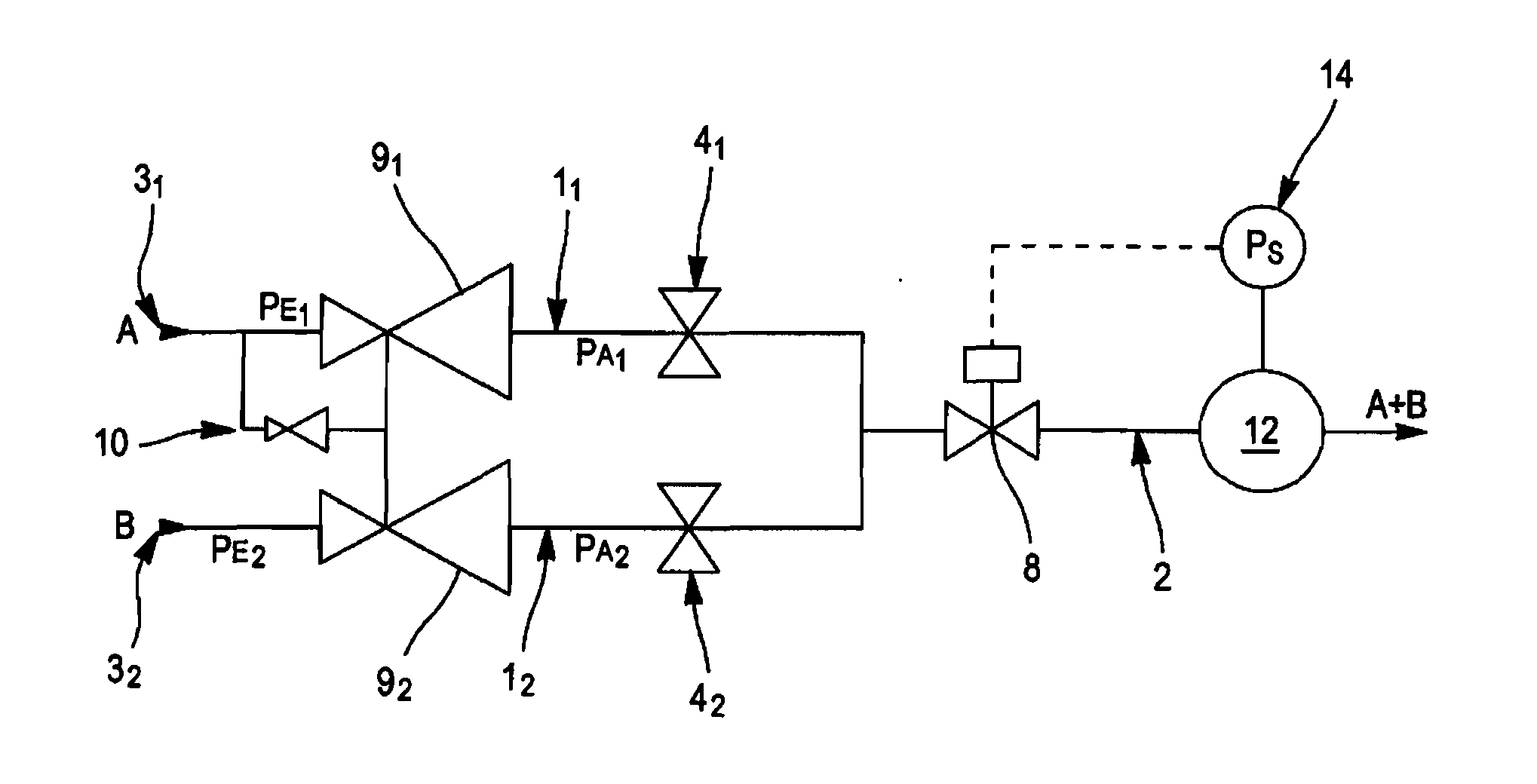
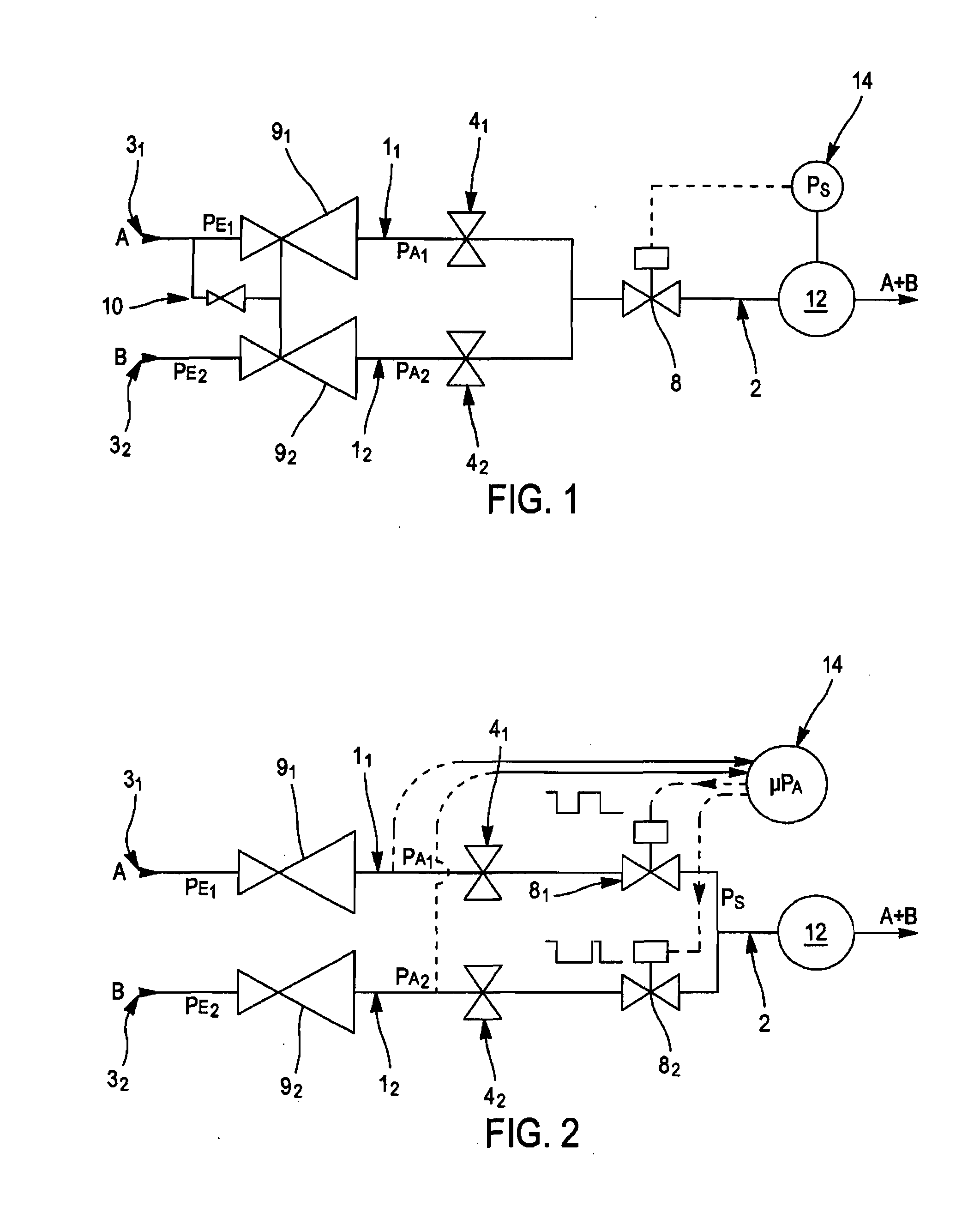
[0024]Such a device for mixing at least two gaseous components comprises at least two arms 1 of a pneumatic circuit arranged in parallel and each being suitable for receiving 3 a gaseous component at a given supply pressure PE and for supplying a joint output line 2 of the desired mixture. According to the invention and what is shown in the attached figures:

[0025]each arm comprises a means for adjusting 4 the flow of the component in question to a determined constant value that depends at least on the supply pressure PA of the component,

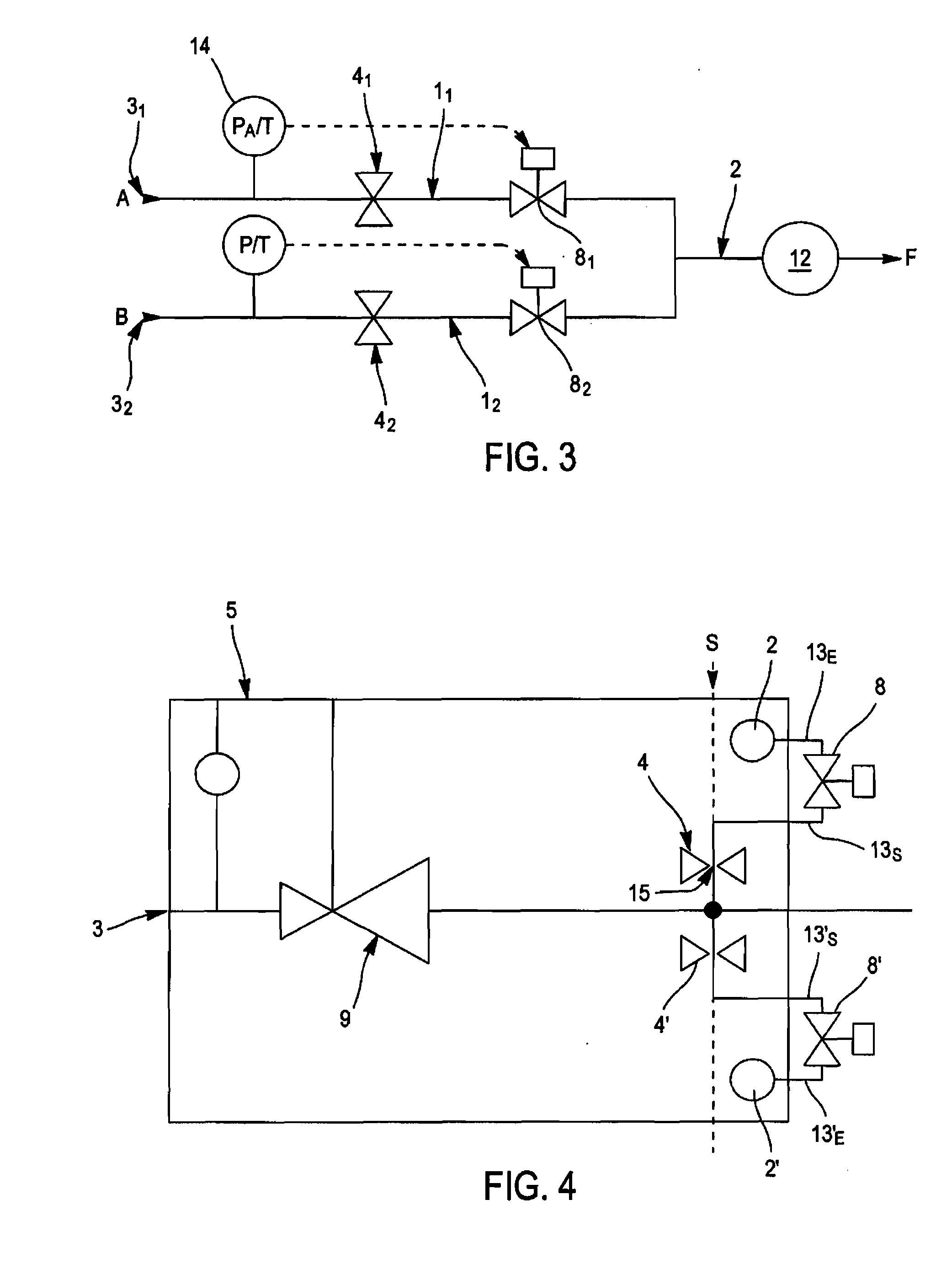
[0026]each arm 1 is realized in a polyhedral block 11 made of a material that is tight to the diverse gaseous components and resistant to their supply pressure, comprising at least two opposing flat surfaces 6 to which the intake and / or output collectors 7 of at least the portion of the pneumatic circuit that makes up said 1 connect.

[0027]As shown in FIG. 5, all of the conduits and collectors of this pneumatic circuit are realized by piercing the bl...


PUM

PropertyMeasurementUnit
pressureaaaaaaaaaa
inlet pressureaaaaaaaaaa
pressure PEaaaaaaaaaa

Abstract

A device for mixing at least two gaseous components having at least two arms of a pneumatic circuit arranged in parallel and each being suitable for receiving one gaseous component, and for supplying a joint output line with the desired mixture. Each arm comprises a unit for adjusting the flow of the component in question and is made in a polyhedral block of a gastight material comprising at least two opposing flat surfaces to which the intake and output collectors of at least the portion of the pneumatic circuit that makes up said arm connect; said polyhedral blocks of each arm are brought together by assembling one flat surface of one block against a flat surface of the other block.

Description

BACKGROUND[0001]This invention has for object a device for mixing at least two gaseous components in order to obtain a gaseous mixture containing a desired predetermined proportion of each of said gaseous components.[0002]The technical sector of the invention is the realization of such mixing devices, also known as “gas mixers” of which there are many types for which is certain cases patent applications have been filed.[0003]A first family includes the so-called static devices comprised of a chamber wherein a determined quantity of each gaseous component is injected and action is then taken in order to obtain a homogeneous mixture: this type of device does not make it possible, on the one hand to obtain the desired mixture immediately nor continuously and, on the other hand, requires the implementation of substantial means.[0004]Another family of so-called dynamic devices consists in injecting flows servo-controlled by direct measurements of the content of each component in the mixt...

Claims


Application Information

Patent Timeline
Patent Type & Authority Applications(United States)
IPC IPC(8): F15D1/00B01F23/10
CPCB01F3/026B01F5/0077B01F15/00162B01F15/00175G05D11/132B01F15/00344B01F15/00935B01F15/0412B01F15/00207Y10T137/877B01F23/19B01F25/105B01F35/2113B01F35/2115B01F35/213B01F35/2211B01F35/561B01F35/83
Inventor MUSSOT, JEAN-LUC
Owner AKHEA
Why Eureka
Try Eureka