Projectile having one or more windows for transmitting power and/or data into/from the projectile interior

Active Publication Date: 2012-01-05
OMNITEK PARTNERS LLC
View PDF0 Cites 1 Cited by
  • Summary
  • Abstract
  • Description
  • Claims
  • Application Information

AI Technical Summary

Benefits of technology

[0006]Accordingly, a projectile is provided. The projectile comprising: a casing; first and second windows provided on the casing for at least one of transmitting a first optical signal into an interior of the casing and transmitting a second optical signal from the interior of the casing; a receiving element disposed on the interior of the casing and in optical communication with one or mor

Problems solved by technology

Transmitting data and / or power to and / or from the projectile prior to firing thereof may be a cumbersome process, particularly where the projectile has had a relatively long shelf life.

Method used


Image

  • Projectile having one or more windows for transmitting power and/or data into/from the projectile interior
  • Projectile having one or more windows for transmitting power and/or data into/from the projectile interior
  • Projectile having one or more windows for transmitting power and/or data into/from the projectile interior

Examples


Embodiment Construction

[0025]Although the invention is particularly suited to infra-red or optical signal communication between electronic components, such is discussed by way of example only. Those skilled in the art will appreciate that other communication means can also be utilized, such as ultrasound.

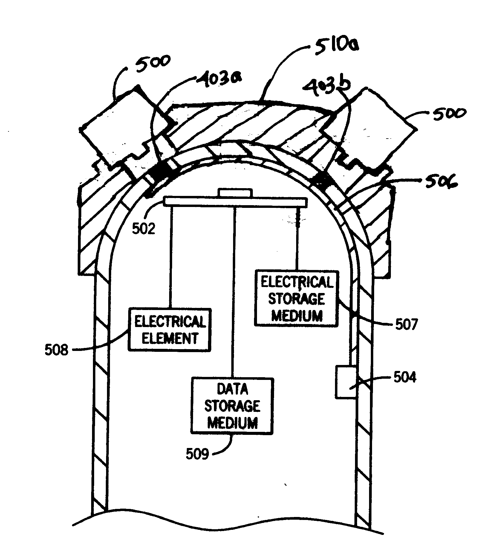
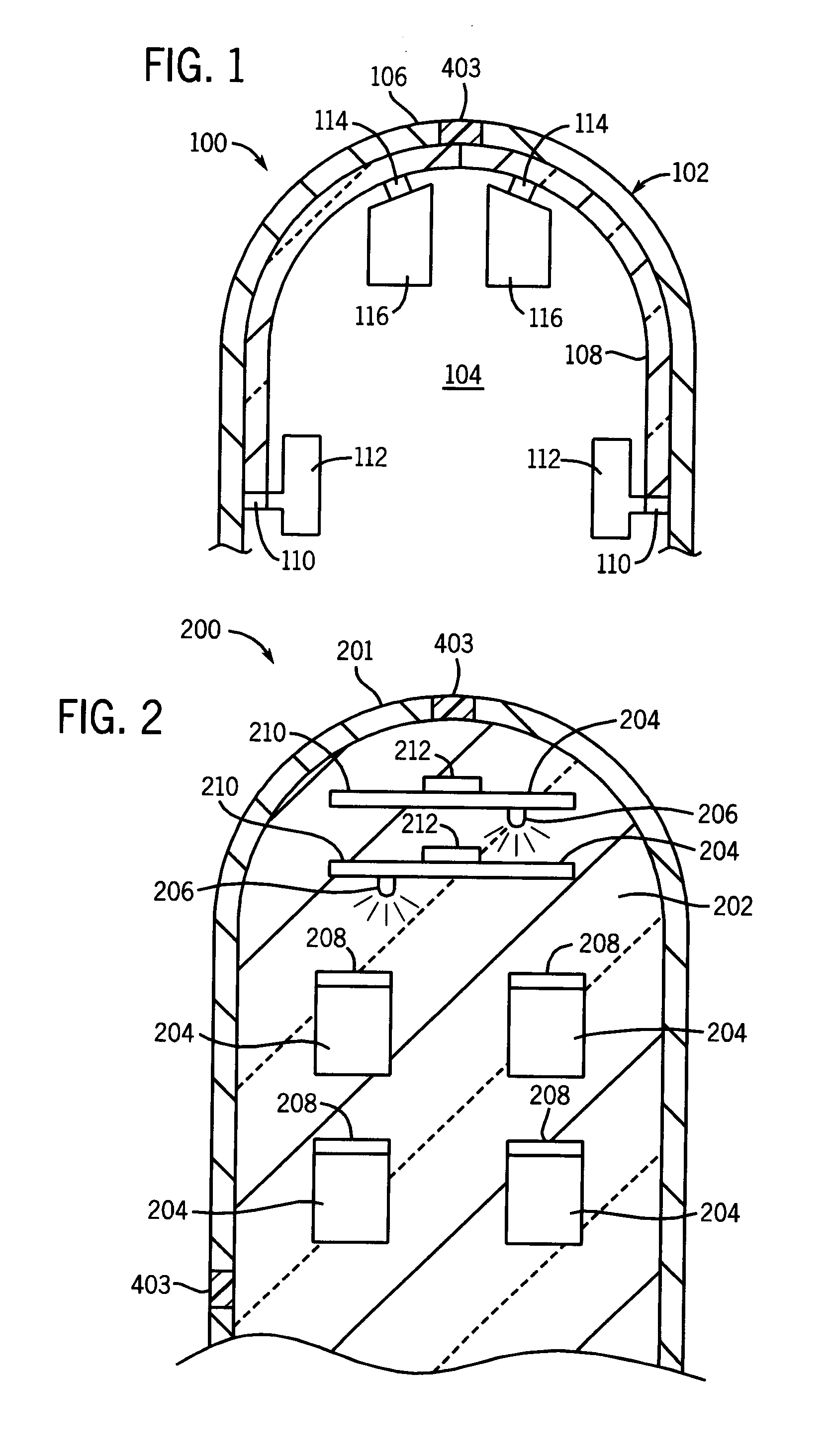
[0026]Referring now to FIG. 1, there is shown a partial sectional view of a nose section of a projectile 100. The projectile has a shell 102 that defines an interior 104. The shell preferably has a metal or composite outer portion 106 and an inner waveguide portion 108. The inner waveguide portion 108 is preferably optical glass having appropriate cladding as is known in the art, however, other at least partially transparent materials such as plastics capable of transmitting a signal can also be utilized, such as clear epoxies. The waveguide portion 108 can be disposed on the entire inner surface of the outer portion 106 or only a portion thereof, such as a strip. Alternatively, the waveguide portion 108 ...


PUM


Abstract

A projectile including: a casing; first and second windows provided on the casing for at least one of transmitting a first optical signal into an interior of the casing and transmitting a second optical signal from the interior of the casing; a receiving element disposed on the interior of the casing and in optical communication with one or more of the first and second windows for at least one of converting the first optical signal into electrical energy and storing data provided in the first optical signal; and a transmitting element disposed on the interior of the casing and in optical communication with one or more of the first and second windows for transmitting data provided in the second optical signal to outside the casing.

Description

CROSS-REFERENCE TO RELATED APPLICATION[0001]This application is a Continuation-In-Part Application of U.S. application Ser. No. 12 / 206,704 filed on Sep. 8, 2008, which is a Continuation-In-Part Application of U.S. application Ser. No. 11 / 080,260 filed on Mar. 15, 2005, which is a Continuation-In-Part of U.S. application Ser. No. 10 / 638,996 filed on Aug. 12, 2003, the entire contents of each of which is incorporated herein by reference.BACKGROUND OF THE INVENTION[0002]1. Field of the Invention[0003]The present invention relates generally to projectiles, and more particularly, to projectiles having a window on a portion of the casing of the projectile for transmitting data and / or power through said window. For purposes of this disclosure, a projectile is any flying object, such as munitions, rockets, or aircraft.[0004]2. Prior Art[0005]Projectiles typically have a casing or shell in which electronic / electrical components are housed. Transmitting data and / or power to and / or from the pr...

Claims


Application Information

Patent Timeline
IPC IPC(8): F42B15/01
CPCF42B12/365F42B12/382F41G7/007H04L12/40045F42B15/08F42B15/01
Inventor RASTEGAR, JAHANGIR S.
Owner OMNITEK PARTNERS LLC
Why Eureka
Try Eureka