Three-axis pedestal having motion platform and piggy back assemblies

a technology of three-axis pedestals and piggybacks, which is applied in the direction of machine supports, other domestic objects, mechanical apparatus, etc., can solve the problems of fluidic tilt sensors not being able to be mounted directly to the antenna, antennas mounted on the ship will tend to be misdirected, and other environmental stresses

Active Publication Date: 2012-01-05
SEA TEL INC D B A COBHAM SATCOM
View PDF3 Cites 48 Cited by
  • Summary
  • Abstract
  • Description
  • Claims
  • Application Information

AI Technical Summary

Benefits of technology

[0024]One of the primary and secondary may include a feed assembly including a remotely adjustable polarizer. The remotely adjustable polarizer may include a tubular-body that

Problems solved by technology

When a ship changes its geographical position, or when the satellite changes its position in orbit, and when the ship rolls, pitches, yaws and turns, an antenna mounted on the ship will tend to become misdirected.
In addition to these disturbances the antenna will be subjected to other environmental stresses such as vibrations caused by shipboard machinery and shocks caused by wave pounding.
As an antenna system's pointing angle can change from 0° to 90°, however, such fluidic tilt sensors can not be mounted directly to the antenna, Instead, the fluidic tilt sensor must be mounted in a structure that is rotated opposite the antenna pointing angle so that the structure always remains in an attitude that is substantially level with respect to the local hori

Method used


Image

  • Three-axis pedestal having motion platform and piggy back assemblies
  • Three-axis pedestal having motion platform and piggy back assemblies
  • Three-axis pedestal having motion platform and piggy back assemblies

Examples


Embodiment Construction

[0048]Reference will now be made in detail to various embodiments of the present invention(s), examples of which are illustrated in the accompanying drawings and described below. While the invention(s) will be described in conjunction with exemplary embodiments, it will be understood that present description is not intended to limit the invention(s) to those exemplary embodiments. On the contrary, the invention(s) is / are intended to cover not only the exemplary embodiments, but also various alternatives, modifications, equivalents and other embodiments, which may be included within the spirit and scope of e invention as defined by the appended claims.

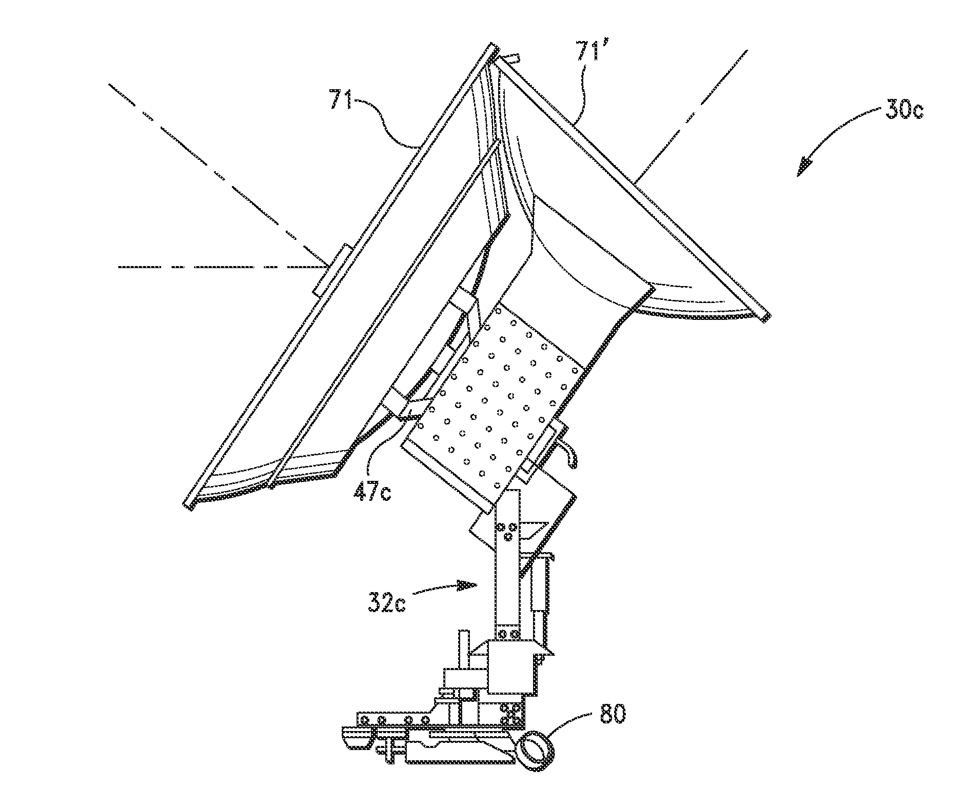
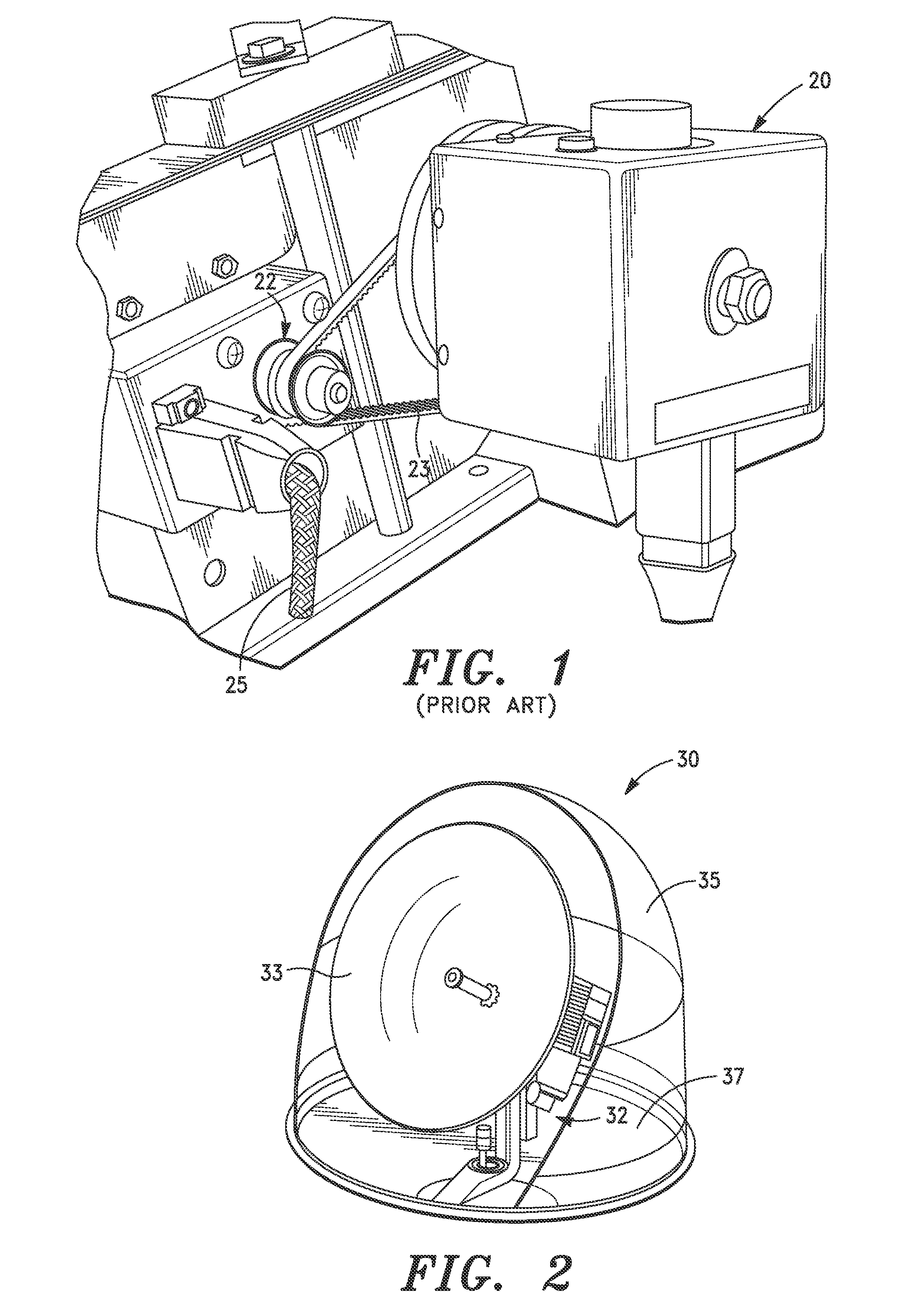
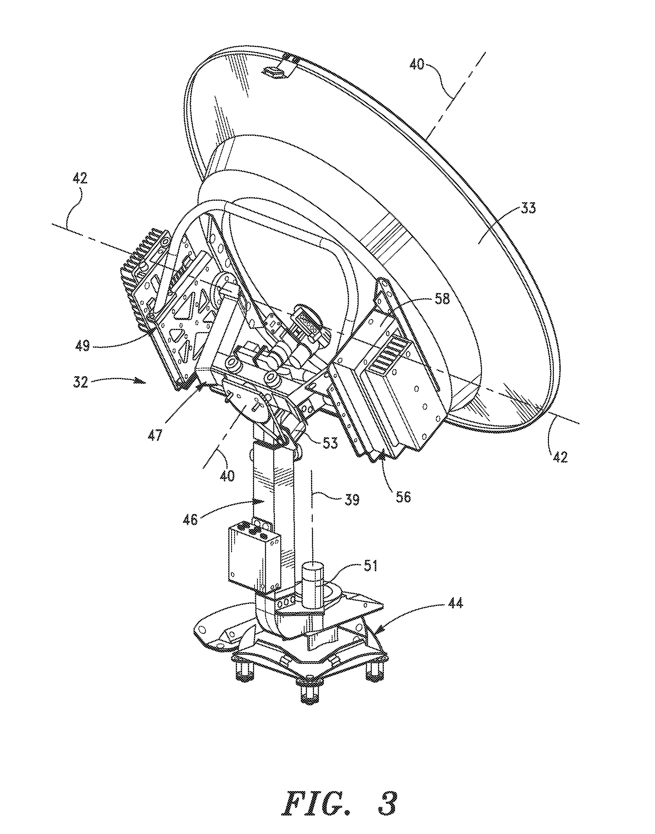
[0049]In its simplest form the present invention includes supporting structural members, bearings, and drive means for positioning various rotating and pivoting structural members which are configured to align a tracking antenna about three axis, an azimuth axis, a cross-level axis, and an elevation axis. Antenna stabilization is achiev...


PUM


Abstract

A rotationally-stabilizing tracking antenna system suitable for mounting on a moving structure includes a three-axis pedestal for supporting an antenna about a first azimuth axis, a second cross-level axis, and a third elevation axis, a three-axis drive assembly for rotating a vertical support assembly relative to a base assembly about the first azimuth axis, a cross-level driver for pivoting a cross-level frame assembly relative to the vertical support assembly about the second cross-level axis, and an elevation driver for pivoting an elevation frame assembly relative to the cross-level frame assembly about the third elevation axis, a motion platform assembly affixed to and movable with the elevation frame assembly, three orthogonally mounted angular rate sensors disposed on the motion platform assembly for sensing motion about predetermined X, Y and Z axis of the elevation frame assembly, a three-axis gravity accelerometer mounted on the motion platform assembly and configured to determine a. true-gravity zero reference, and a control unit for determining the actual position of elevation frame assembly based upon the sensed motion about said predetermined X, Y, and Z axes and said true-gravity zero reference, and for controlling the azimuth, cross-level and elevation drivers to position the elevation frame assembly in a desired position. Instead of or in addition to the motion platform assembly, the antenna system may include primary and secondary antenna affixed relative to the cross-level frame assembly and a control unit for selecting operation of a selected on of the primary and secondary antennas, determining the actual position of elevation frame assembly based upon the sensed motion about said predetermined X, Y, and Z axes, and for controlling the azimuth, cross-level and elevation drivers to position the selected one of the primary and secondary antennas in a desired position for tracking a communications satellite. Methods of using the three-axis pedestal having motion platform assembly is also described.

Description

CROSS-REFERENCE TO RELATED APPLICATIONS[0001]This application claims priority to U.S. Provisional Patent Application No. 61 / 358,938 filed on Jun. 27, 2010 and to U.S. Provisional Patent Application No. 61 / 452,639 filed on Mar. 14, 2011, the entire contents of which are incorporated herein for all purposes by this reference.BACKGROUND OF THE INVENTION[0002]1. Field of the Invention[0003]This invention relates, in general, to pedestals for tracking antenna and more particularly to satellite tracking antenna pedestals used on ships and other mobile applications and methods for their use.[0004]2. Description of Related Art[0005]The invention is especially suitable for use aboard ship wherein an antenna is operated to track a. transmitting station, such as a communications satellite, notwithstanding roll, pitch, yaw, and turn motions of a ship at sea.[0006]Antennas used in shipboard satellite communication terminals typically are highly directive. For such antennas to operate effectively...

Claims


Application Information

Patent Timeline
IPC IPC(8): F16M11/18H01Q3/00
CPCH01Q25/00H01Q3/08H01Q1/34H01Q1/125H01Q3/00H01Q3/02H01Q1/185
Inventor BLANEY, PETER
Owner SEA TEL INC D B A COBHAM SATCOM
Why Eureka
Try Eureka