Detection system and method for detecting movements of a movable object

Active Publication Date: 2012-01-05
NXP BV
View PDF14 Cites 11 Cited by
  • Summary
  • Abstract
  • Description
  • Claims
  • Application Information

AI Technical Summary

Benefits of technology

[0008]It is an object of the invention to provide a detection system and a method for detecting movements of the kind set forth, which do not suffer from the slip-away problem. This object is achieved by the detection system according to claim 1 and the method according to claim 11.
[0009]The inventor has recognized that the slip-away problem is caused by the following behavior of the system. The movable object, i.e. a knob which is hung by a spring, serves both tilt and click operations. In other words, the knob is used to determine movements in the X and Y directions, which are used, for example, to steer the movement of a cursor on a display, but also for movements in the Z direction, which are used to select a target item on the display to which the cursor has moved by performing a click operation. An ideal click operation is performed only if the click force is perfectly applied to the center of the knob and in a perfectly vertical direction. However, in practice the click force is either not perfectly vertical and / or not exactly applied at the center point of the knob. This results in a lateral force component applied to the knob during a click action, which produces a torque on the rotation point of the spring that slightly tilts the reflecting unit, besides moving it downward. As a consequence, the differential signal in the X and / or Y direction(s) becomes non-zero and shortly after that returns to zero again when the reflecting unit is in the fully clicked down position. In other words, unintentional tilt movement is detected in the X and / or Y direction(s), which results in the slip-away problem. The slip-away problem is annoying for the user because the target item on the display is missed just when the click signal, based on movement in the Z direction, is generated. This is an inherent property of the spring; therefore it is not possible to solve the problem by mechanical design. The basic concept of the invention is therefore that the detection system and the corresponding method for detecting movements of the knob compensate for unintentional tilt movement of the knob in the X and / or Y direction(s) when a linear movement in the third direction (Z) is detected.

Problems solved by technology

However, in practice the click force is either not perfectly vertical and / or not exactly applied at the center point of the knob.
This results in a lateral force component applied to the knob during a click action, which produces a torque on the rotation point of the spring that slightly tilts the reflecting unit, besides moving it downward.
In other words, unintentional tilt movement is detected in the X and / or Y direction(s), which results in the slip-away problem.
The slip-away problem is annoying for the user because the target item on the display is missed just when the click signal, based on movement in the Z direction, is generated.
This is an inherent property of the spring; therefore it is not possible to solve the problem by mechanical design.

Method used


Image

  • Detection system and method for detecting movements of a movable object
  • Detection system and method for detecting movements of a movable object
  • Detection system and method for detecting movements of a movable object

Examples


Embodiment Construction

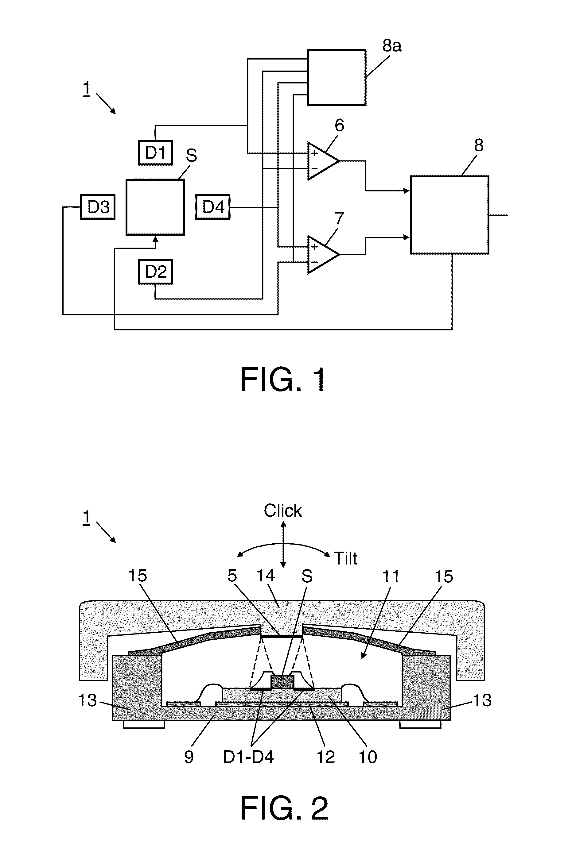
[0025]FIG. 1 shows an overall configuration of the circuitry of an optical joystick (detection system) which is known from WO 2010 / 035170 A1.

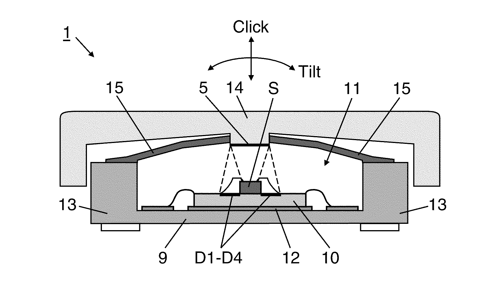
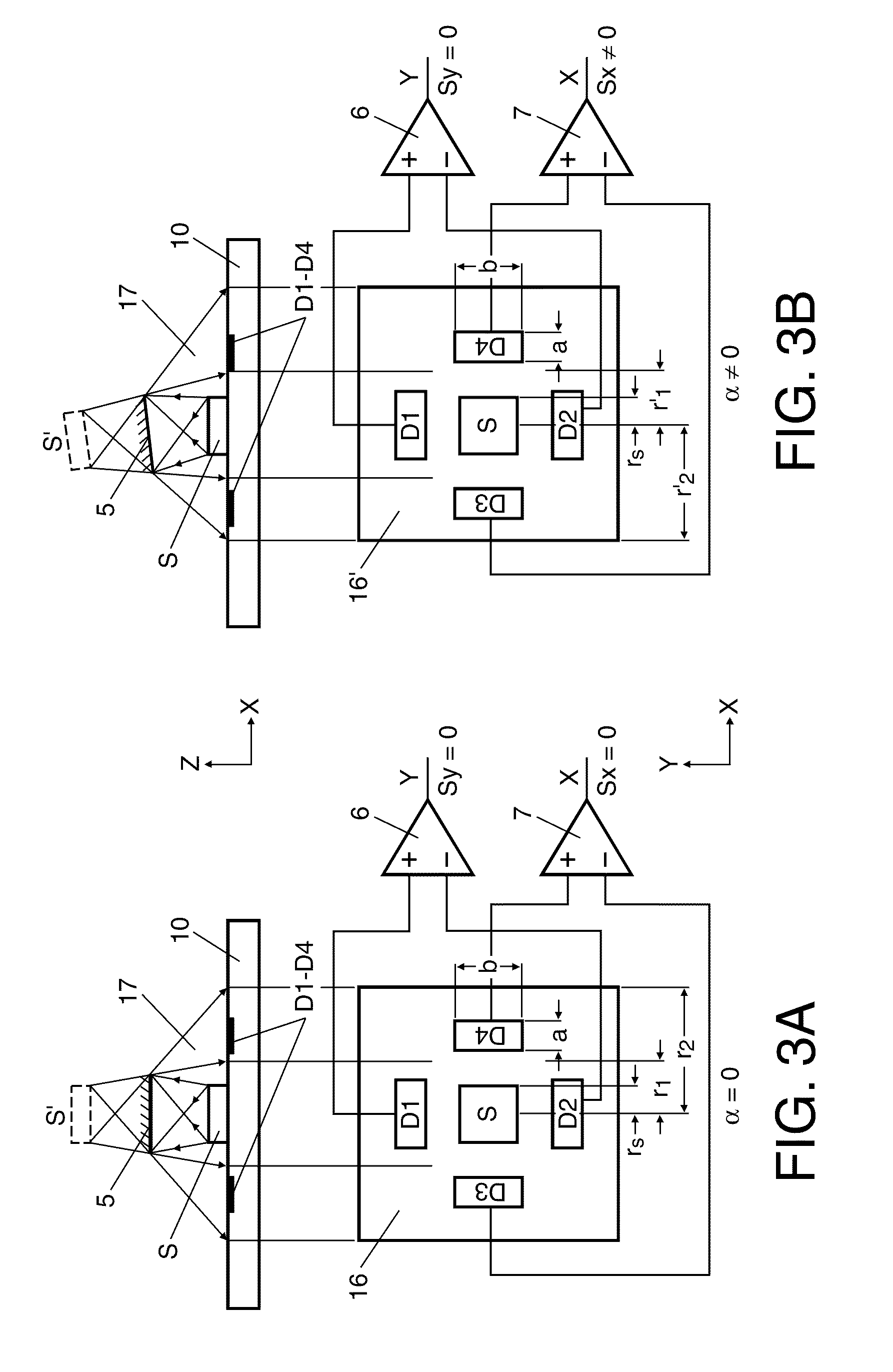
[0026]According to FIG. 1, a plurality of photosensitive devices such as light detectors (or photodetectors) hereinafter referred to as detectors D1 to D4 and having the function (sensing function) of a light receiving means is provided according to a predetermined arrangement. The arrangement of FIG. 1 shows, for example, the detectors D1 to D4, but the arrangement is not limited to this number of detectors since any suitable number n of detectors D1 to Dn can be provided. Each of the detectors D1 to D4 may be composed of a plurality of particular light sensitive elements, such as photo diodes or photo transistors. A light emitting element or light emitting means, hereinafter referred to as a light source S, is provided adjacent to the plural detectors D1 to D4, and is arranged for emitting a light which can be reflected by a reflecting unit 5...


PUM


Abstract

The present invention concerns a detection system and a corresponding method for detecting movements of a movable object that compensate for unintentional tilt movement of the movable object in a first direction and / or in a second direction when a linear movement in a third direction is detected.

Description

[0001]This application claims the priority under 35 U.S.C. §119 of European patent application no. 10168405.8, filed on Jul. 5, 2010, the contents of which are incorporated by reference herein.FIELD OF THE INVENTION[0002]The invention relates to a detection system for the detection of movements of a movable object. The invention also relates to a method for detecting movements of a movable object of a detection system. The invention further relates to an integrated circuit having implemented therein a detection system for detecting the movements of a movable object. Finally, the invention relates to a portable device comprising a detection system for the detection of movements of a movable object.BACKGROUND OF THE INVENTION[0003]In recent years the market for mobile devices such as mobile phones, PDAs, has grown enormously. The diversity in functionalities and user interfaces has also increased.[0004]Existing mobile devices usually have a display (for example a Liquid Crystal Displa...

Claims


Application Information

Patent Timeline
IPC IPC(8): G06F3/041H01J40/14G06F3/0338G06F3/038
CPCG06F3/0304G06F3/038G06F3/0338
Inventor PHAN LE, KIM
Owner NXP BV
Why Eureka
Try Eureka