Method and System for Determining Projections in Non-Central Catadioptric Optical Systems

a catadioptric optical system and projection technology, applied in the field of catadioptric optical systems, can solve the problems of skewed 3d estimation, no analytical solution for projection for non-central catadioptric systems, and incorrect solutions

Inactive Publication Date: 2012-01-05
MITSUBISHI ELECTRIC RES LAB INC
View PDF4 Cites 4 Cited by
  • Summary
  • Abstract
  • Description
  • Claims
  • Application Information

AI Technical Summary

Benefits of technology

[0016]Some embodiments determine a reflection points on the surface of the mirror by solving a 6th degree equation for a general conic mirror. For a spherical mirror, the complexity of the equation is reduced to a 4th degree equation, resulting in a closed form solution. The

Problems solved by technology

However, there is no analytical solution of projection for non-central catadioptric systems.
However, those methods lead to inaccuracie

Method used


Image

  • Method and System for Determining Projections in Non-Central Catadioptric Optical Systems
  • Method and System for Determining Projections in Non-Central Catadioptric Optical Systems
  • Method and System for Determining Projections in Non-Central Catadioptric Optical Systems

Examples


Embodiment Construction

[0026]Method and System Overview

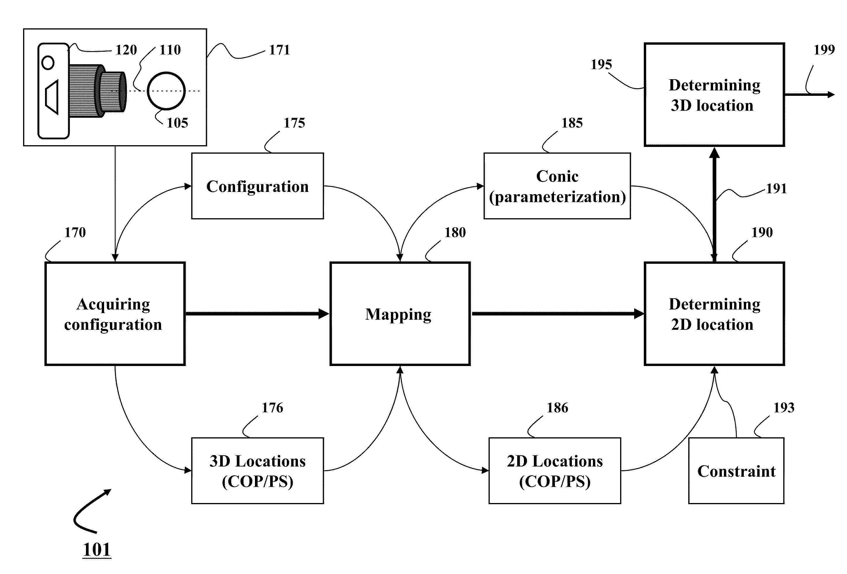
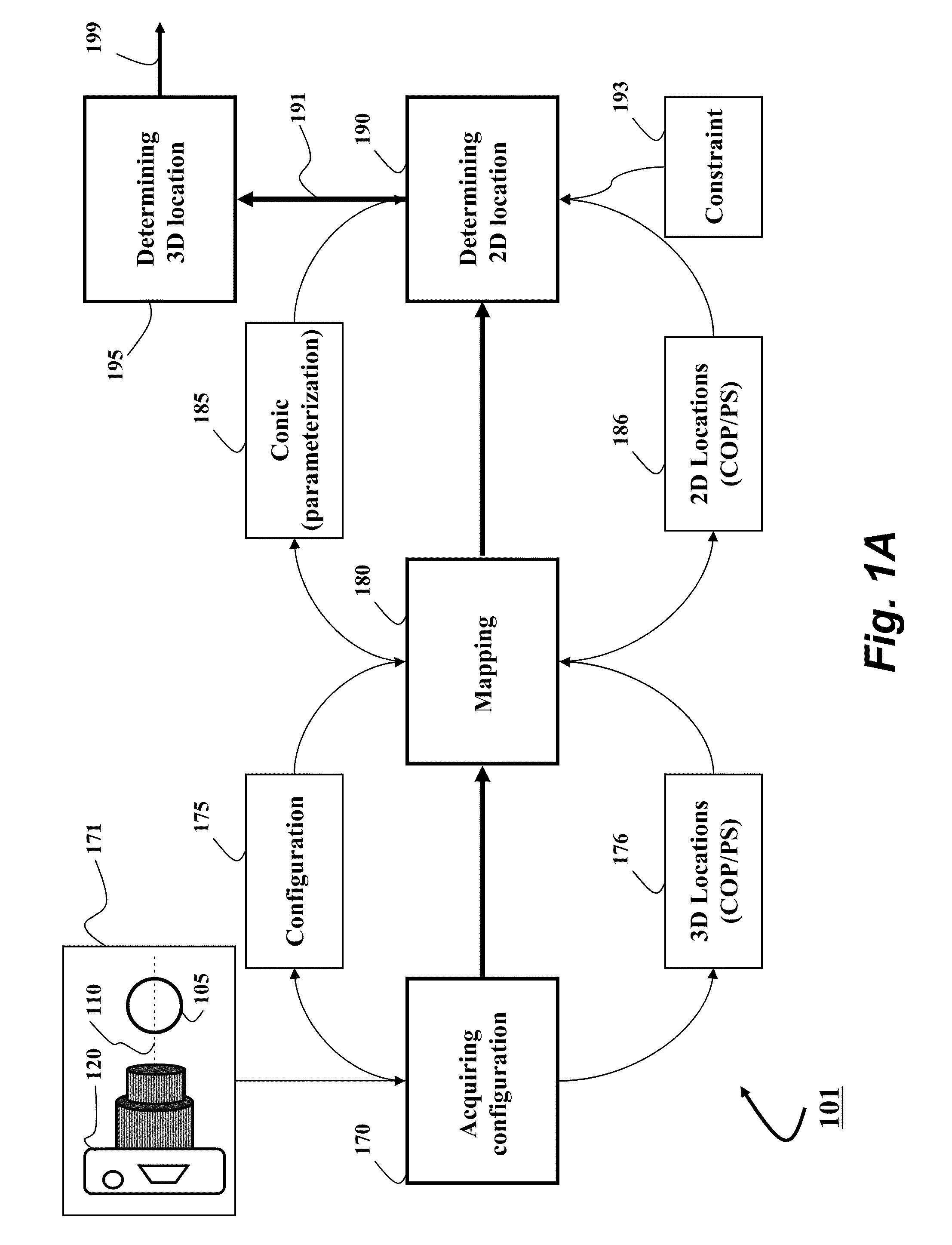
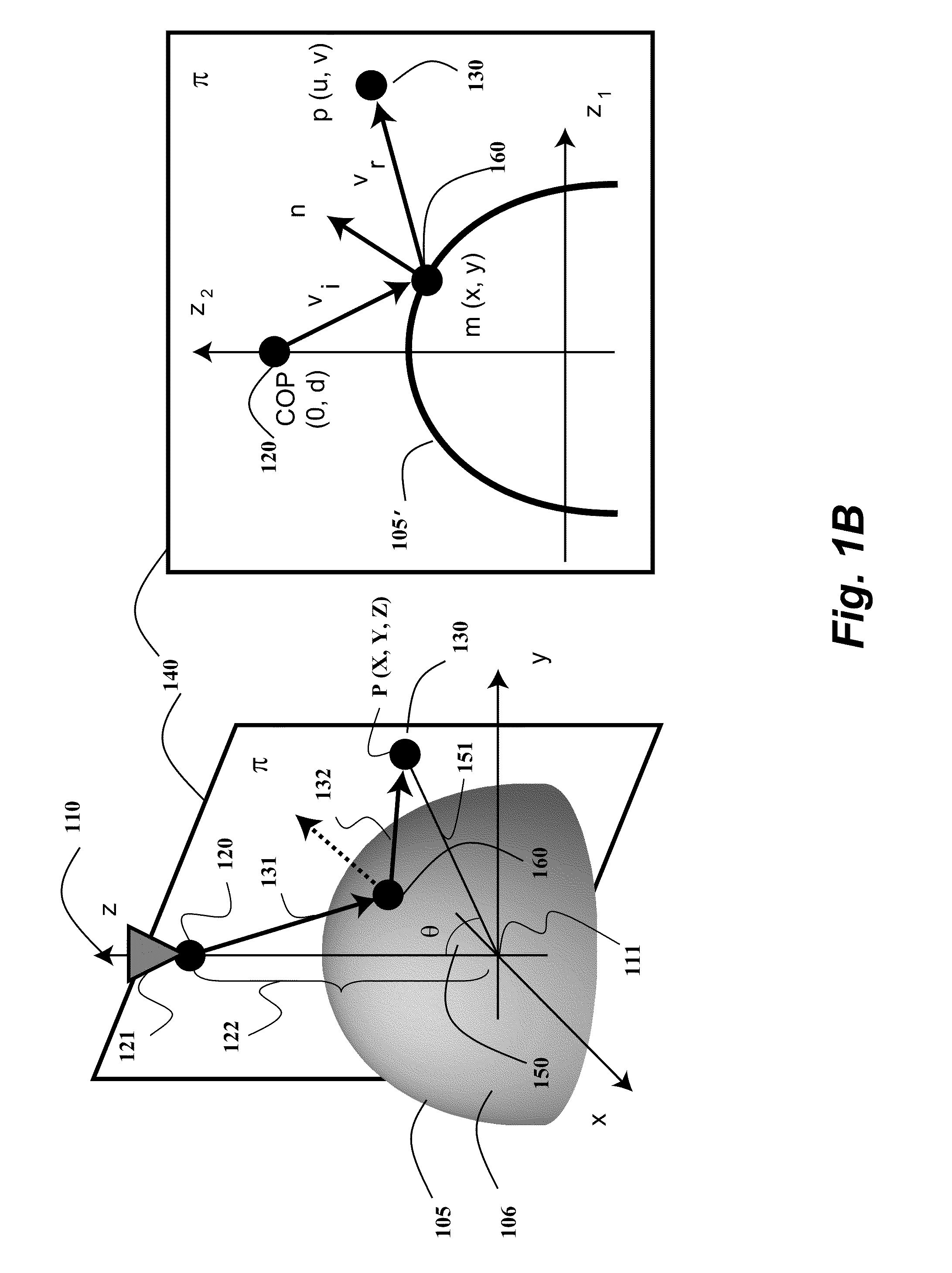
[0027]Embodiments of invention are based on a realization that a three-dimensional (3D) projection of a point in a scene (PS) for particular configurations of a non-central catadioptric optical system can be determined analytically by mapping a 3D structure of the catadioptric system on a two-dimensional (2D) plane defined by an axis of symmetry of the catadioptric system and the PS.

[0028]Such configurations include non-central catadioptric systems having a camera arranged at a distance from a surface of a reflector or a refractor, wherein the surface is quadric and rotationally symmetric around an axis of symmetry, and a center of projection (COP) of the camera used in the catadioptric system is arranged on the axis of symmetry. The 2D plane is defined by the axis of symmetry, and the PS and 2D solution of the projection represents the 3D projection, in part, due to the rotational symmetry of the catadioptric system.

[0029]FIG. 1A shows a block diagra...


PUM


Abstract

Embodiment of invention discloses a system and a method for determining a three-dimensional (3D) location of a folding point of a ray between a point in a scene (PS) and a center of projection (COP) of a camera of a catadioptric system. One embodiment maps the catadioptric system, including 3D locations of the PS and the COP on a two-dimensional (2D) plane defined by an axis of symmetry of a folding optical element and the PS to produce a conic and 2D locations of the PS and COP on the 2D plane, and determines a 2D location of the folding point on the 2D plane based on the conic, the 2D locations of the PS and the COP. Next, the embodiment determines the 3D location of the folding point from the 2D location of the folding point on the 2D plane.

Description

FIELD OF THE INVENTION[0001]This invention relates generally to catadioptric optical systems, and more particularly to determining a projection in non-central catadioptric optical systems.BACKGROUND OF THE INVENTION[0002]A catadioptric optical system combines refraction and reflection principles, usually via lenses (dioptrics) and curved mirrors (catoptrics). The catadioptric system includes camera imaging reflectors or refractors enabling wide field-of-view (FOV) imaging. The catadioptric systems have been used in a wide range of applications, including panoramic imaging and visualization, wide-angle reconstruction, surveillance, and mobile robot and car navigation. The catadioptric system can be central or non-central.[0003]Central Catadioptric System[0004]Central catadioptric systems use a single camera-mirror pair arranged to enable an effective single viewpoint, i.e., all rays of light forming an image acquired by the camera sensor intersect at one point. Examples of the centra...

Claims


Application Information

Patent Timeline
IPC IPC(8): G02B17/08
CPCG02B27/0012G02B17/08
Inventor TAGUCHI, YUICHIAGRAWAL, AMIT K.RAMALINGAM, SRIKUMAR
Owner MITSUBISHI ELECTRIC RES LAB INC
Why Eureka
Try Eureka