Battery array configured to prevent vibration

a battery array and vibration prevention technology, applied in the field of battery arrays, can solve the problems of inability to reliably prevent various detrimental effects, and difficulty in reliably preventing up-and-down vibration of rectangular battery cells held between the binding bars, so as to achieve simple battery array assembly, prevent relative vibration between separators and binding bars, and prevent rectangular battery cell vibration

Active Publication Date: 2012-01-05
SANYO ELECTRIC CO LTD
View PDF1 Cites 39 Cited by
  • Summary
  • Abstract
  • Description
  • Claims
  • Application Information

AI Technical Summary

Benefits of technology

[0012]In the battery array of the present invention, the separators 2 can have insertion grooves 24 that fit with the binding bars 4, and the binding bars 4 can be inserted in the insertion grooves 24. In this battery array, relative vibration between the separators and the binding bars can be prevented by inserting the binding bars in the separator insertion grooves. As a result, rectangular battery cell vibration can be effectively prevented while enabling simple battery array assembly.
[0013]In the battery array of the present invention, the separators 2 can have insertion grooves 24 at the top or bottom on both sides, binding bars 4 can have an L-shaped cross-section configured with a vertical section 41 that aligns with the sides of the battery stack 5 and a horizontal section 42 that fits in the insertion grooves 24, and the horizontal sections 42 can be inserted in the insertion grooves 24. In this battery array, since the horizontal sections of the L-shaped binding bars are inserted in separator insertion grooves, the binding bars and separators become reliably linked in a structure with no relative vibration between its elements. In addition, the vertical and horizontal bending strength of the binding bars is increased to achieve the characteristic that the battery stack can be robustly held together with the binding bars.
[0014]In the battery array of the present invention, binding bars 4 can be disposed at the top and bottom on both sides of the battery stack 5. In this battery array, since both sides of the battery stack are held together at the top and bottom by binding bars, the plurality of stacked rectangular battery cells can be held together more robustly and rectangular battery cell vibration can be prevented more effectively.
[0015]In the battery array of the present invention, each rectangular battery cell 1 can be provided with a metal external case 11, and the surface of the metal external case 11 can be covered with an insulating layer 16. This battery array is characterized by insulating the metal

Problems solved by technology

With this battery array, it is difficult to reliably prevent up-and-down vibration of the rectangular battery cells held between the binding bars.
In particular, when used in a vibration inducing environment such as in a vehicle, rectangular battery cell vibration cannot be reliably prevented.
In this situation, vibration of the centrally located rectangular battery leads to various detrimental effects.
For example, insulating layers established on the surfaces of vibrating rectangular battery cells can rub against non-vibrating binding bars to cause leakage currents or insul

Method used


Image

  • Battery array configured to prevent vibration
  • Battery array configured to prevent vibration
  • Battery array configured to prevent vibration

Examples


Embodiment Construction

[0030]The following describes embodiments of the present invention based on the figures.

[0031]As an embodiment of the present invention, the following describes an example of battery arrays used in a power source apparatus installed on-board a vehicle to supply power to a motor that drives the vehicle. The following description is based on FIGS. 1-7.

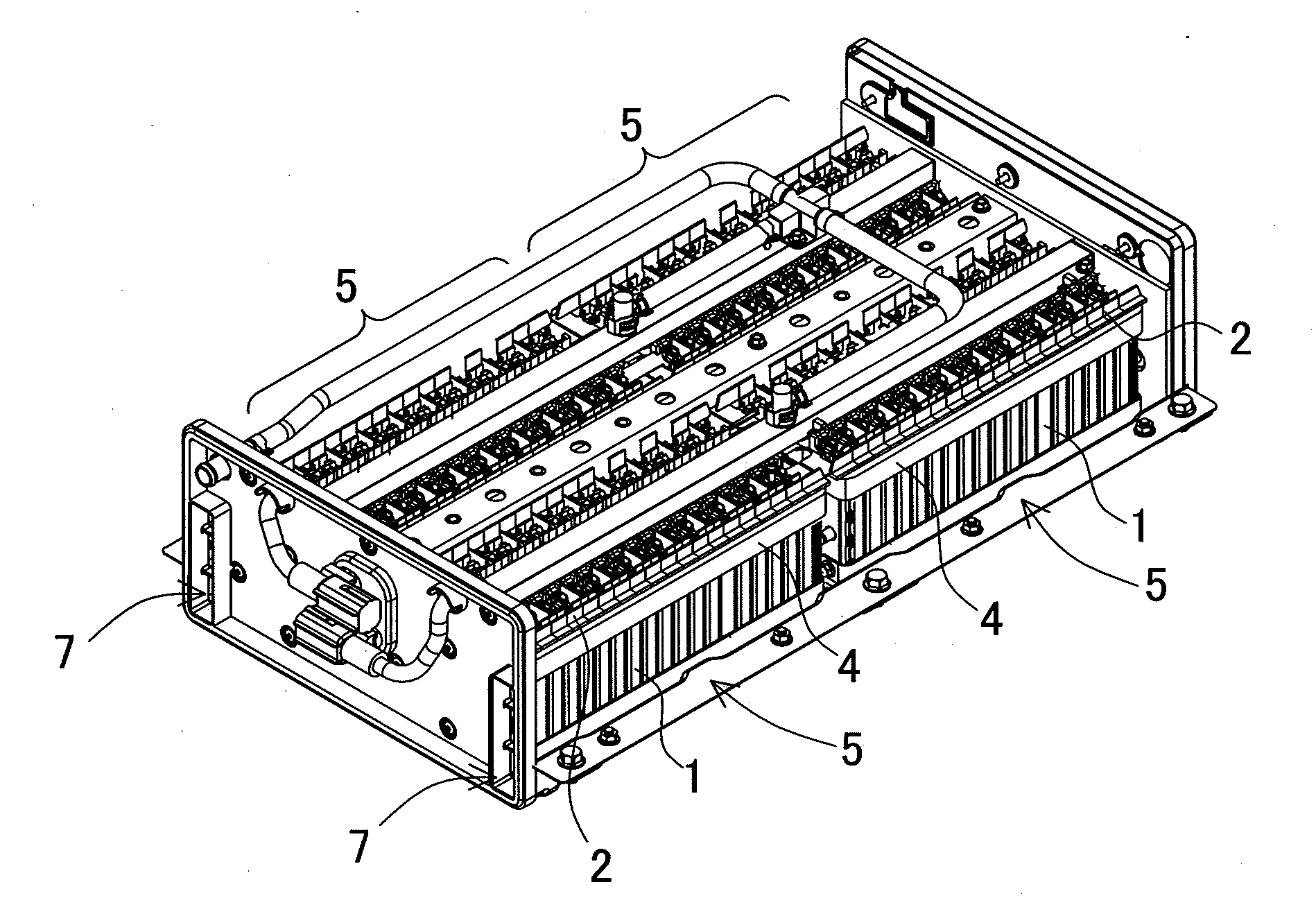
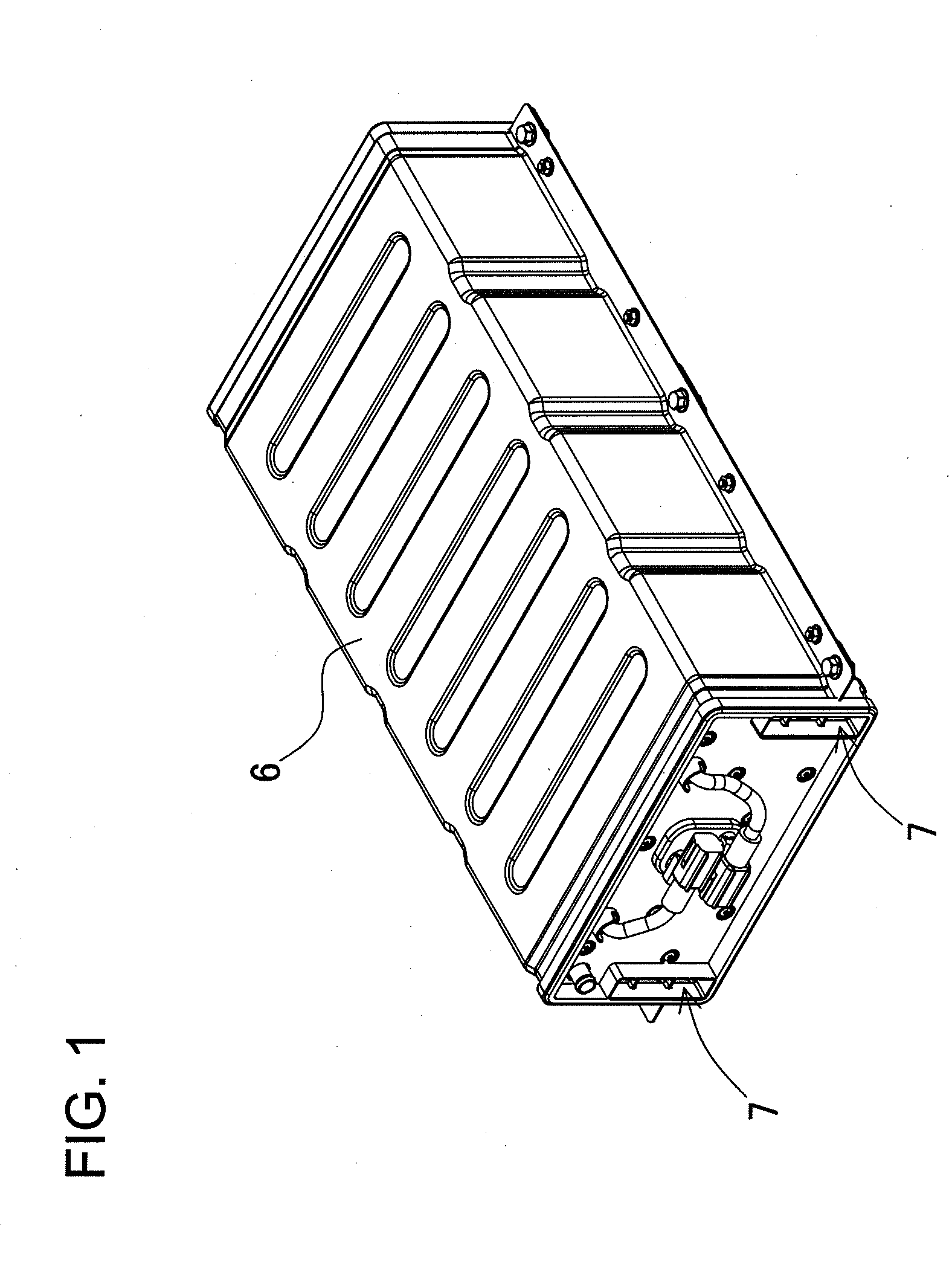
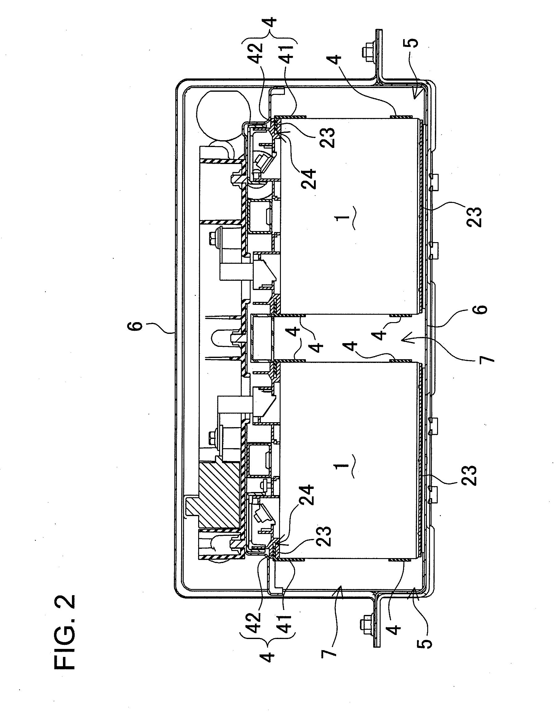
[0032]Battery arrays are housed in an outer case 6 and installed as a power source apparatus in a vehicle. Cooling ducts 7 are established between the battery arrays and the outer case 6 to cool rectangular battery cells 1 in the battery arrays. Forced ventilation cools the rectangular battery cells 1 by introducing cooling gas into the cooling ducts 7 and between the separators 2 and rectangular battery cells 1.

[0033]As shown in FIGS. 4-6, a battery array is made up of a battery stack 5 having of a plurality of rectangular battery cells 1 stacked together with intervening separators 2. Separators 2 act as spacers that form cooling gaps ...


PUM


Abstract

The battery array is provided with a battery stack 5 having a plurality of rectangular battery cells 1 stacked together with intervening separators 2, endplates 3 disposed at the ends of the battery stack 5, and binding bars 4 extending in the battery cell 1 stacking direction and attached to the endplates 3 in a manner that binds both sides of the battery stack 5. The binding bars 4 are configured as plates of given width extending along the battery stack 5 surfaces. The binding bars 4 and separators 2 fit together in a linked configuration that limits their relative movement in the up-and-down direction.

Description

BACKGROUND OF THE INVENTION[0001]1. Field of the Invention[0002]The present invention relates to a battery array having a plurality of rectangular battery cells stacked with intervening separators, and in particular to a battery array optimally suited as a power source installed on-board an electric-powered vehicle such as a hybrid vehicle (hybrid car) or electric vehicle (electric automobile) to supply power to a motor that drives the vehicle.[0003]2. Description of the Related Art[0004]A battery array for automotive applications has many battery cells connected in series to increase output voltage and power. Considering charging capacity per unit volume, a battery array has been developed that arranges many rectangular battery cells in a stack.[0005]For example, refer to Japanese Laid-Open Patent Publication 2010-86887.[0006]In the battery array cited in JP 2010-86887, angled binding bars are attached to retain the rectangular battery cells in a stack. The ends of the binding bars...

Claims


Application Information

Patent Timeline
IPC IPC(8): H01M2/10H01M10/60H01M10/613H01M10/625H01M10/647H01M10/6557H01M10/6563H01M50/119H01M50/124H01M50/209H01M50/264H01M50/291H01M50/293
CPCH01M2/0262H01M2/028H01M2/1077H01M10/0481H01M10/441H01M2220/20H01M10/5016H01M10/5018H01M10/5032H01M10/5059H01M10/5067H01M10/5004H01M10/625H01M10/6563H01M10/6557H01M10/627H01M10/613H01M10/647Y02E60/10Y02P70/50H01M50/293H01M50/209H01M50/264H01M50/291H01M50/124H01M50/119H01G11/10H01G11/12H01G11/08H01G11/82H01G11/78Y02T10/70
Inventor KUME, MASAOMURAKAMI, TOSHIYUKI
Owner SANYO ELECTRIC CO LTD
Why Eureka
Try Eureka