
Multi-purpose armored vehicle

a multi-purpose, armored technology, applied in the field of armored vehicles, can solve the problems of limited options for police and similar enforcement officials, and achieve the effects of reducing the risk of death or bodily harm, compactness, and increasing the safety of individuals on approach

Inactive Publication Date: 2012-01-12
HALL KENNITH
View PDF0 Cites 2 Cited by
  • Summary
  • Abstract
  • Description
  • Claims
  • Application Information

AI Technical Summary

Benefits of technology

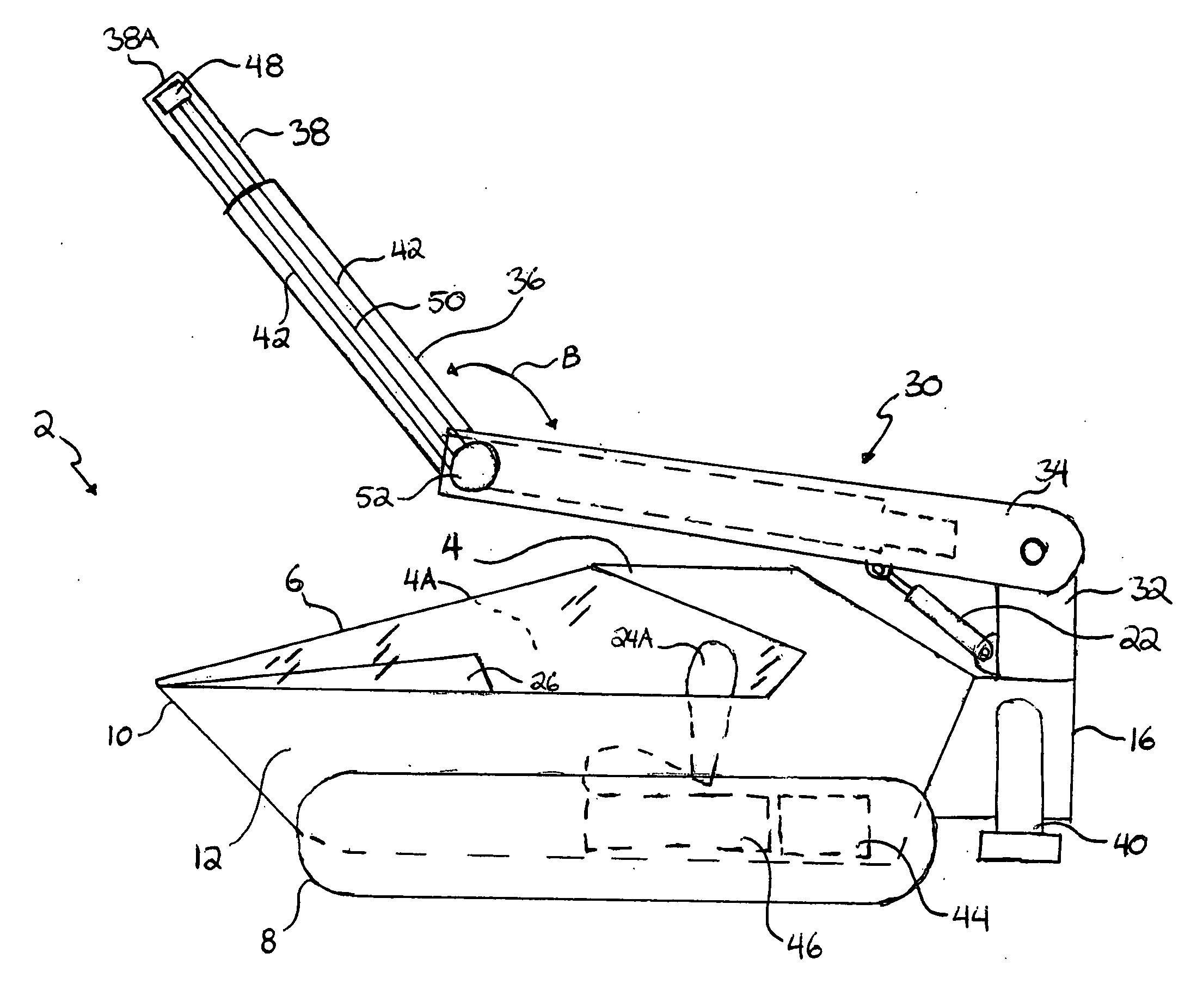
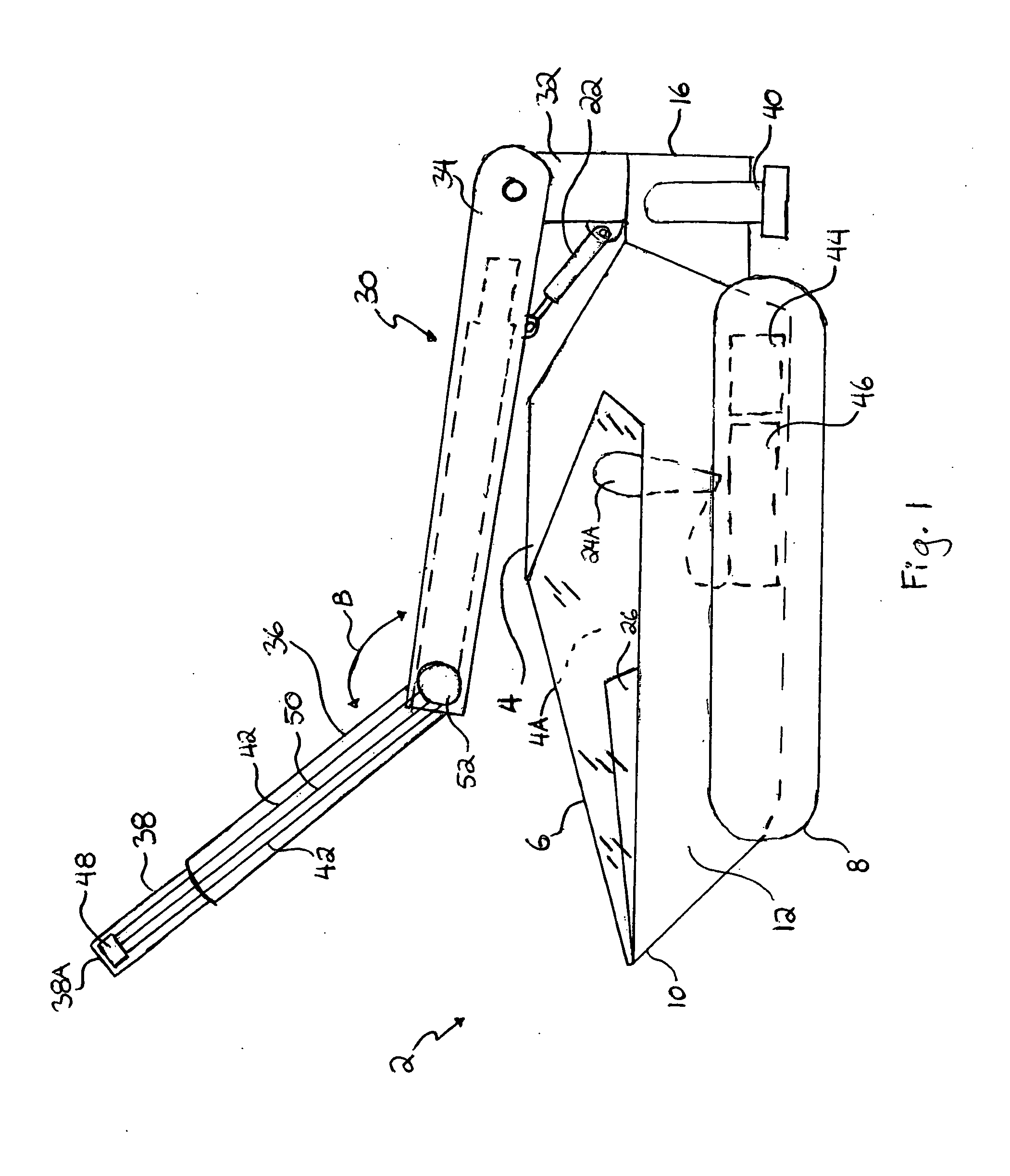
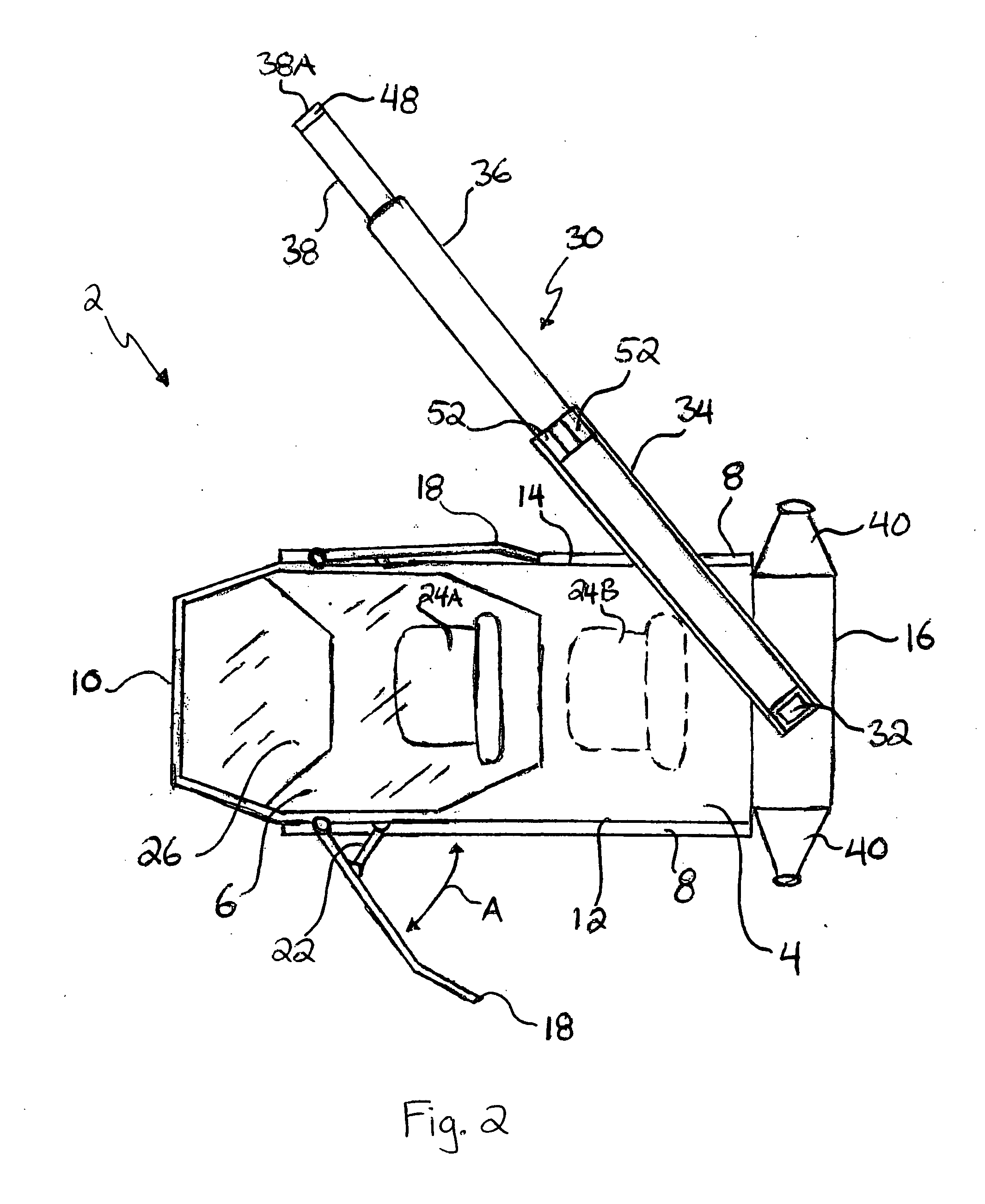
[0022]Police, and similar enforcement officials, have limited options when in a standoff with criminals. Often hostages are involved so that police are reluctant to rush the criminals or use measures that might harm the hostages. The police also do not wish to be harmed. The present invention provides a solution to this by providing a multi-purpose armored vehicle configured to be used for security purposes such as patrols, alarm responses, protection of critical transactions, hostage situations, and bomb threat support. The vehicle is armor-plated and provides a bullet- and explosion-proof glass canopy which covers an entrance to an air-tight operator's compartment capable of accommodating one or two people. In addition, the vehicle is sufficiently compact so as to enable clearance and passage through standard gates, doorways, and living areas. Thus, a police officer can approach a suspect or criminal in the vehicle and initiate a safe face-to-face discussion using a microphone and speaker built into the vehicle. This is psychologically superior to simply speaking to the suspect by phone.
[0023]A pair of armor-plated shields are pivotally engaged, and selectively positionable, with the sides of the vehicle, allowing a plurality of individuals to travel alongside the vehicle behind the shields while approaching a potentially dangerous situation, thereby substantially increasing the safety of the individuals on approach.
[0024]An extensible boom is engaged with the vehicle. A terminal end of the boom provides a plurality of connectors adapted for removably engaging electric and hydraulic devices. The boom, as well as the devices engaged with the connectors, are configured for being controlled from within the safety of the operator's compartment. A pair of audio-visual devices, including a video monitor, camera, microphone, and speaker, may be engaged with connectors within the operator's compartment and on the boom respectively. This allows for simulated face-to-face communications between the operator within the operator's compartment and a suspect in proximity to the terminal end of the boom, while the vehicle is positioned out of harm's way, which is also psychologically superior to simply speaking to the suspect by phone.
[0025]A wide range of electric and hydraulic devices may be removably engaged with the connectors of the vehicle. Hydraulic arms may be engaged with the boom, allowing an operator of the vehicle to approach and disarm bombs or handle radioactive materials. Water jets, pepper spray, loud speakers, munitions, and other lethal and non-lethal weapons may also be engaged with the boom, allowing an operator of the vehicle to subdue a suspect or suppress a large crowd of rioters. These are merely examples of the various devices that may be engaged with the present invention in order to accomplish an array of tasks while simultaneously decreasing the risk of death or bodily harm for all parties involved.
[0029]A still further objective is to provide such an apparatus that provides an air-tight cockpit to protect the vehicle's occupants from contaminated air outside the vehicle.
[0034]A still further objective is to provide such an apparatus that is constructed in such a way and with such materials as to provide for less than a 3-pound-per-square-inch weight burden on the supporting structure upon which the vehicle may traverse.

Problems solved by technology

Police, and similar enforcement officials, have limited options when in a standoff with criminals.

Method used


Image

  • Multi-purpose armored vehicle
  • Multi-purpose armored vehicle
  • Multi-purpose armored vehicle

Examples


Embodiment Construction

[0039]The above described drawing figures illustrate the described apparatus and its method of use in at least one of its preferred, best mode embodiment, which is further defined in detail in the following description. Those having ordinary skill in the art may be able to make alterations and modifications to what is described herein without departing from its spirit and scope. Therefore, it must be understood that what is illustrated is set forth only for the purposes of example and that it should not be taken as a limitation in the scope of the present apparatus and method of use.

[0040]Described now in detail is a multi-purpose vehicle apparatus. As shown in FIGS. 1 and 2, the apparatus comprises a vehicle 2 having a body 4 which defines a front aspect 10, opposing medial side aspects 12, a distal rear aspect 16, and a top aspect 14. In addition, the body encloses an operator's compartment 4A, having an entrance proximal to the top aspect 14. The body 4 is armor plated and, prefe...


PUM


Abstract

A multi-purpose armored vehicle is configured for a wide range of purposes by military and police units and in both defensive and offensive postures. A protective canopy covers an entrance to a cockpit capable of accommodating at least one person. The vehicle is sufficiently narrow to enable it to pass through conventional gates and also doorways to, and within buildings. A pair of armor-plated shields are pivotally engaged, and selectively positionable, with the sides of the vehicle, allowing shelter to personnel traveling alongside the vehicle. An extensible boom may be fitted with a wide range of hardware including weapons and communications equipment for dealing with situations involving criminals, terrorists, etc. The shields, boom movement and extension, and hardware are all controllable from the cockpit.

Description

CROSS-REFERENCE TO RELATED APPLICATIONS[0001]Not applicable.STATEMENT REGARDING FEDERALLY SPONSORED RESEARCH OR DEVELOPMENT[0002]Not applicable.THE NAMES OF THE PARTIES TO A JOINT RESEARCH AGREEMENT[0003]Not applicable.INCORPORATION-BY-REFERENCE OF MATERIAL SUBMITTED ON A COMPACT DISC[0004]Not applicable.REFERENCE TO A “MICROFICHE APPENDIX”[0005]Not applicable.SEQUENCE LISTING[0006]Not applicable.BACKGROUND OF THE INVENTION[0007]1. Field of the Present Disclosure[0008]This disclosure relates generally to armored vehicles and, more particularly, to a small, compact, highly maneuverable, multi-purpose armored vehicle configured to be used for security purposes such as patrols, alarm responses, protection of police personnel in critical transactions in hostage situations, and support bomb threat situations.[0009]2. Description of Related Art Including Information Disclosed Under 37 CFR 1.97 and 1.98[0010]Cunningham, US 2005 / 0230163, discloses a motorized vehicle that includes a vehicle...

Claims


Application Information

Patent Timeline
Patent Type & Authority Applications(United States)
IPC IPC(8): B62D55/06H04N7/14F41H7/02
CPCF41H7/00
Inventor HALL, KENNITH
Owner HALL KENNITH
Learn More