Solid-state imaging apparatus and imaging system

a technology of solid-state imaging and imaging equipment, which is applied in the direction of electrical equipment, television system details, television systems, etc., can solve the problems of poor image quality, poor image quality, and variations in power supply potential and ground potential, and achieve the effect of suppressing image quality degradation

Active Publication Date: 2012-01-12
CANON KK
View PDF9 Cites 10 Cited by
  • Summary
  • Abstract
  • Description
  • Claims
  • Application Information

AI Technical Summary

Benefits of technology

[0007]The present invention provides a technique that is advantageous in suppressing image quality degradation caused by variations in the potentials of the power supply line and the ground line.

Problems solved by technology

When the power supply potential and the ground potential vary, noise may be generated in the signal output from the pixel circuit, resulting in poorer image quality.
In addition, an in-pixel readout circuit included in a pixel with a large incident light amount may greatly change the potential of the column signal line and the like, causing variations in the power supply potential and the ground potential, although this does not apply only to the arrangement disclosed in Japanese Patent Laid-Open No. 2002-344809.
This influence may ripple through other pixels and, more particularly, neighboring pixels that share the power supply line and the ground line, leading to degradation in image quality.

Method used


Image

  • Solid-state imaging apparatus and imaging system
  • Solid-state imaging apparatus and imaging system
  • Solid-state imaging apparatus and imaging system

Examples


Embodiment Construction

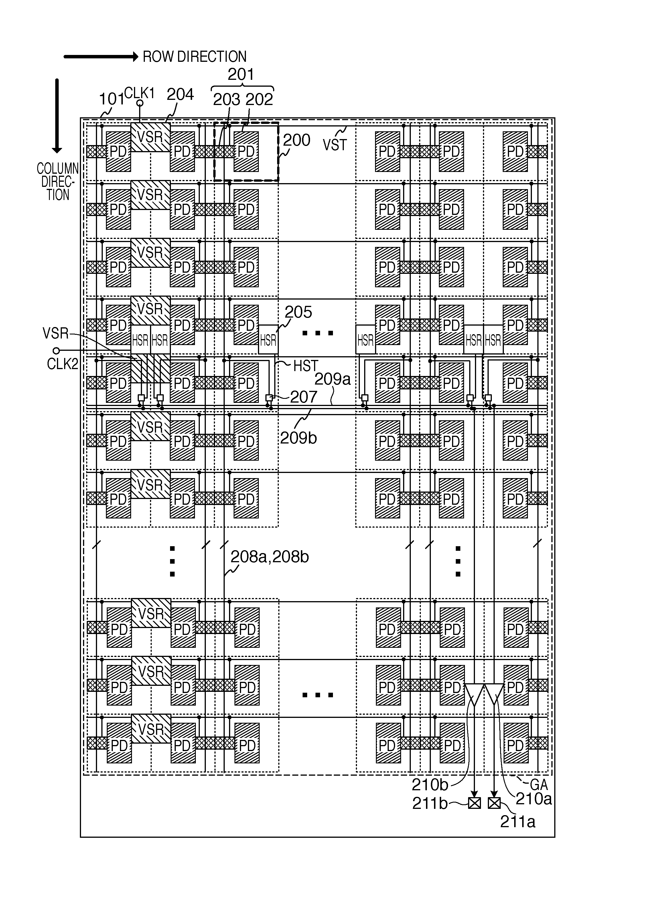
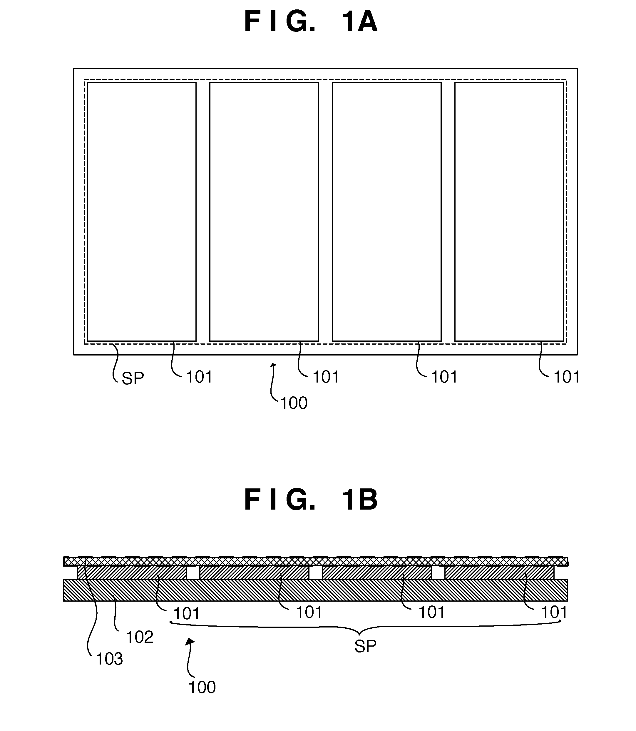
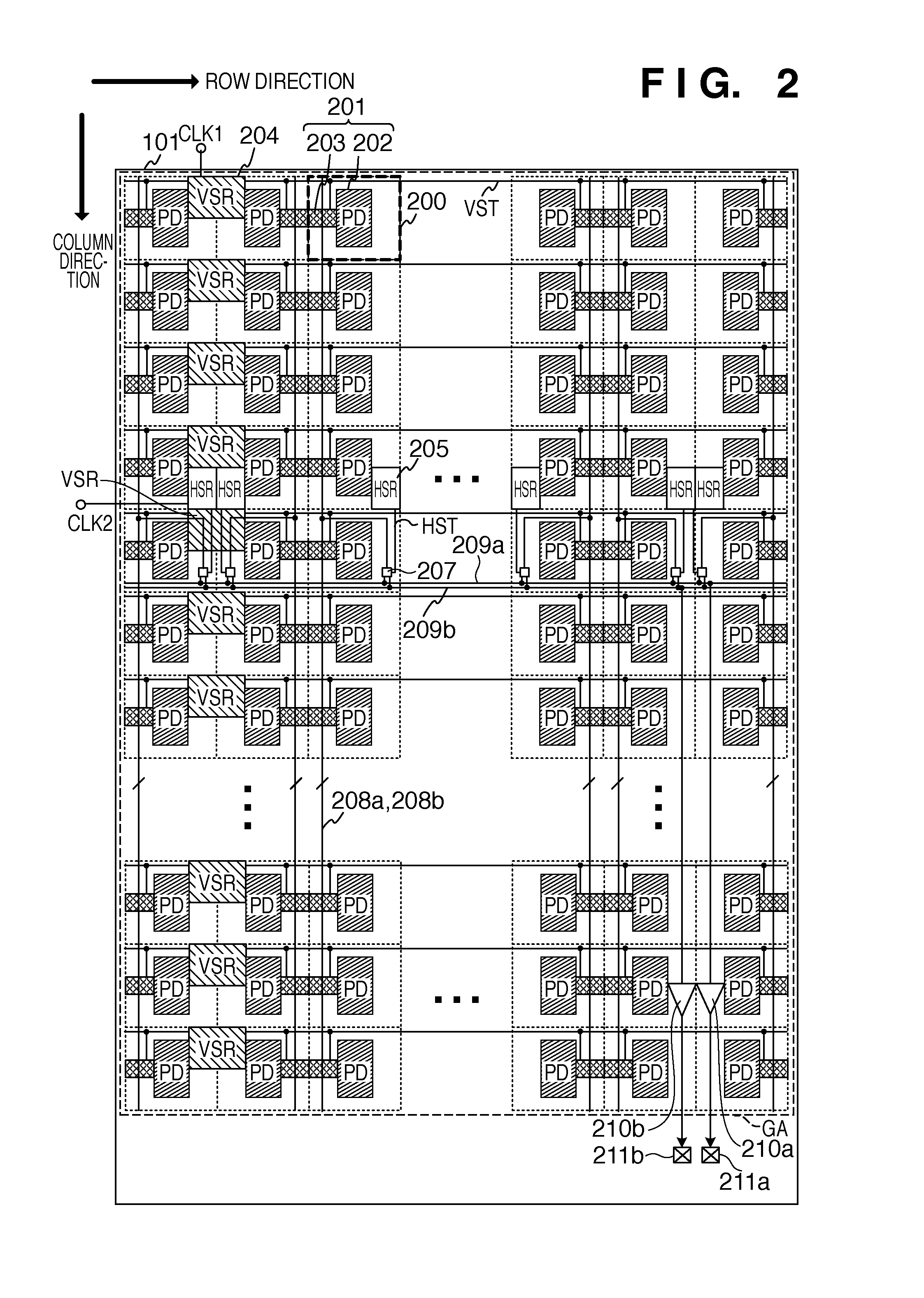
[0021]The schematic arrangement of a solid-state imaging apparatus 100 according to an embodiment of the present invention will be described with reference to FIGS. 1A and 1B. The solid-state imaging apparatus 100 can be formed by, for example, arraying a plurality of imaging blocks 101. In this case, an array of a plurality of imaging blocks 101 can form a sensor panel SP having one imaging region. The plurality of imaging blocks 101 can be arranged on a support substrate 102. When the solid-state imaging apparatus 100 uses a single imaging block 101, the single imaging block 101 forms the sensor panel SP. Each of the plurality of imaging blocks 101 may be provided by, for example, forming a circuit element on a semiconductor substrate or forming a semiconductor layer on, for example, a glass substrate and forming a circuit element on the semiconductor layer. Each of the plurality of imaging blocks 101 has a pixel array in which a plurality of pixels are arrayed so as to form plura...


PUM


Abstract

A solid-state imaging apparatus includes a pixel array in which a plurality of unit cells are arranged to form a plurality of rows and a plurality of columns, wherein each of the plurality of unit cells includes a pixel, and the pixel comprising a photoelectric conversion element and an in-pixel readout circuit which outputs a signal corresponding to charges generated in the photoelectric conversion element, power is supplied to the plurality of unit cells via a power supply line and a ground line, and at least one of the plurality of unit cells includes at least a part of a capacitive element having a first electrode connected to the power supply line and a second electrode connected to the ground line.

Description

BACKGROUND OF THE INVENTION[0001]1. Field of the Invention[0002]The present invention relates to a solid-state imaging apparatus and an imaging system.[0003]2. Description of the Related Art[0004]Japanese Patent Laid-Open No. 2002-344809 discloses an imaging apparatus having vertical shift registers and horizontal shift registers arranged in an image sensor (pixel array). Japanese Patent Laid-Open No. 2002-344809 also discloses an arrangement in which the unit block (the unit to select and drive one row) of vertical shift registers is arranged in one region together with one pixel circuit.[0005]According to the arrangement disclosed in Japanese Patent Laid-Open No. 2002-344809, for example, in the column where the unit block of vertical shift registers is arranged and its neighboring columns, the pixel circuit is susceptible to variations in the power supply potential and the ground potential caused by the operation of the unit block. When the power supply potential and the ground p...

Claims


Application Information

Patent Timeline
Patent Type & Authority Applications(United States)
IPC IPC(8): H04N1/04
CPCH04N5/3745H04N5/357H04N5/32H04N25/60H04N25/77
Inventor FUJIMURA, MASARUKONO, SHOJIYAMASHITA, YUICHIROKIKUCHI, SHINSHIMIZU, SHINICHIROARISHIMA, YU
Owner CANON KK
Why Eureka
Try Eureka