Optical-electrical hybrid transmission cable

Inactive Publication Date: 2012-01-12
HON HAI PRECISION IND CO LTD
View PDF5 Cites 40 Cited by
  • Summary
  • Abstract
  • Description
  • Claims
  • Application Information

AI Technical Summary

Benefits of technology

[0004]Accordingly, an object of the present invention is to provide optical

Problems solved by technology

Recently, as the data transmitting rate between the PC and PC or PC and external electrical device is required faster and faster, the

Method used


Image

  • Optical-electrical hybrid transmission cable
  • Optical-electrical hybrid transmission cable

Examples


Embodiment Construction

[0008]Reference will now be made to the drawing figures to describe the present invention in detail.

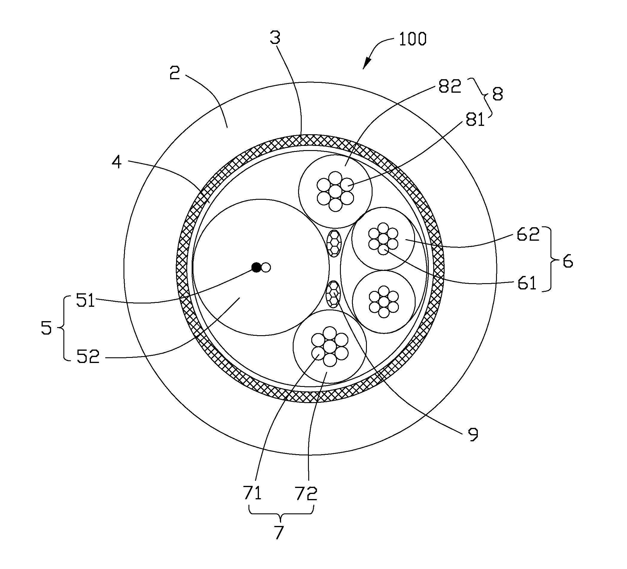
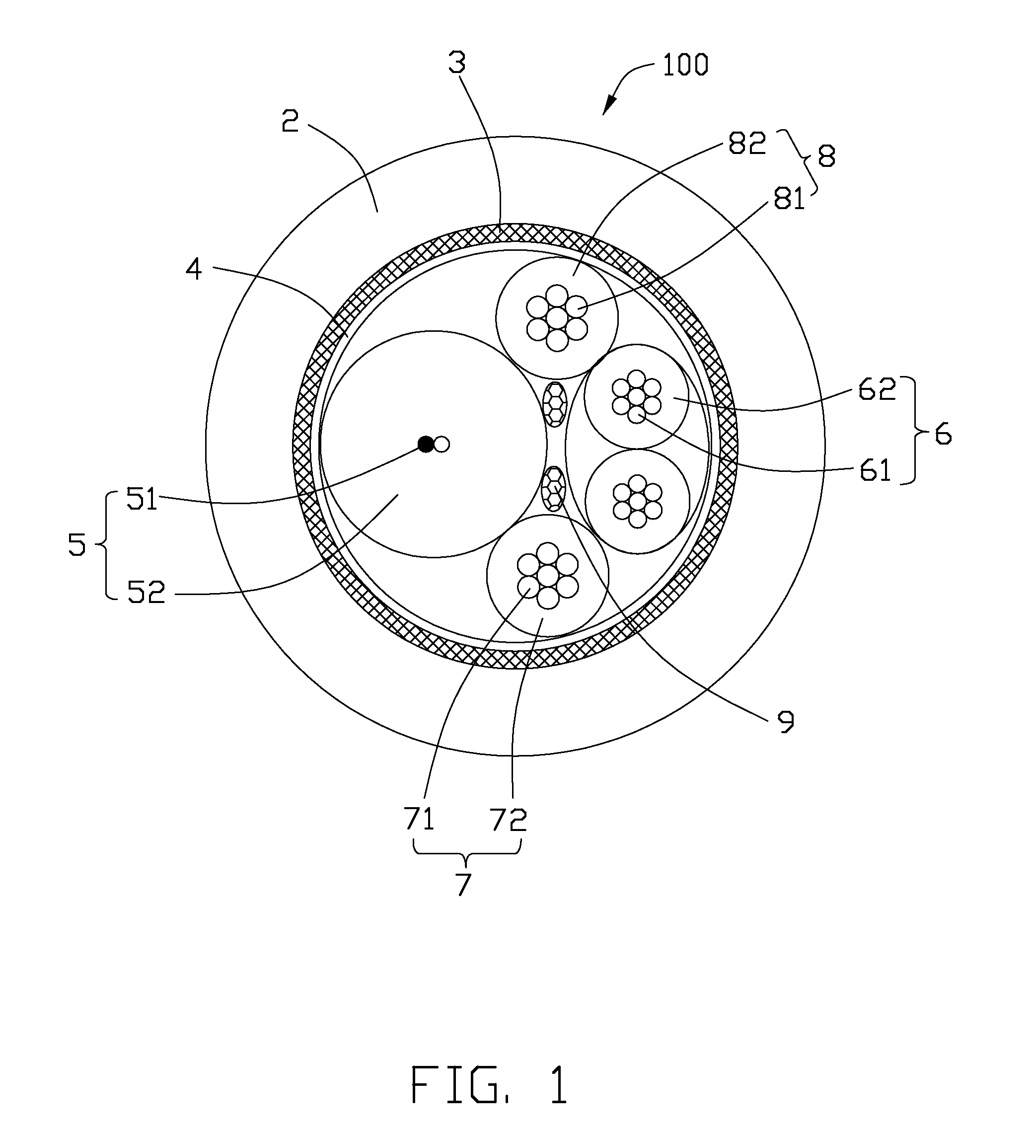
[0009]Referring to FIG. 1, an optical-electrical hybrid transmission cable 100 in accordance with the present invention comprises an insulative layer 2 and a shielding layer from outside to inside, and an optical cable 5, a pair of signal wires 6 twisted together, a pair of power wires 7, 8 disposed in the shielding layer and arranged along a circumferential direction. The optical-electrical hybrid transmission cable 100 further comprises center filled material 9 located between the optical cable 5, the pair of signal wires 6 and the pair of power wires 7, 8. It should be noted that the shielding layer comprises a metallic braided layer 3 and a metallic mylar layer 4 from outside to inside.

[0010]The metallic mylar layer 4 is made of aluminum foil and surrounds the optical cable 5, the pair of signal wires 6 and the pair of power wires 7, 8. The metallic mylar layer 4 is to protect the...


PUM


Abstract

An optical-electrical hybrid transmission cable (100), comprises an insulative layer (2); a shielding layer located on an inner side of the insulative layer; an optical cable (5) disposed in the shielding layer and comprising two optical fibers (51) and an insulative sheath (52) enclosing the two optical fibers; a pair of signal wires (6) twisted together and disposed in the shielding layer; and a pair of power wires disposed in the shielding layer. And the optical cable, the pair of signal wires and the pair of power wires are arranged along a circumferential direction.

Description

FIELD OF THE INVENTION[0001]The present invention relates to a cable, and more particularly to an optical-electrical hybrid transmission cable.DESCRIPTION OF PRIOR ART[0002]Recently, as the data transmitting rate between the PC and PC or PC and external electrical device is required faster and faster, the traditional cable connecting with the PC and PC or PC and external device can not meet the high data transmitting rate requirements.[0003]As discussed above, an improved optical-electrical hybrid transmission cable overcoming the shortages of existing technology is needed.SUMMARY OF THE INVENTION[0004]Accordingly, an object of the present invention is to provide optical-electrical hybrid transmission cable with high speed signals transmission.[0005]In order to achieve the above-mentioned objects, an optical-electrical hybrid transmission cable, comprises an insulative layer; a shielding layer located on an inner side of the insulative layer; an optical cable disposed in the shieldi...

Claims


Application Information

Patent Timeline
IPC IPC(8): G02B6/44H02G3/00
CPCH02G3/0481G02B6/4416
Inventor HAN, WEN-DUYAO, WEITSAO, PEI
Owner HON HAI PRECISION IND CO LTD
Why Eureka
Try Eureka