Structure of USB connector

a technology of connectors and connectors, applied in the direction of connection, electrical apparatus, coupling device connection, etc., can solve the problems of signal error or power voltage instability, more and more difficulties in offering such space for filtering, and defects of the conventional art, so as to save space on the circuit board and reduce the effect of space occupation

Active Publication Date: 2006-01-12
SPEED TECH
View PDF4 Cites 9 Cited by
  • Summary
  • Abstract
  • Description
  • Claims
  • Application Information

AI Technical Summary

Benefits of technology

[0007] It is an object of the present invention, a built-in electric module disposed in an isolation chassis of the connector comprises a signal wave-filter module and a power wave-filter module. The signal wave-filter module and the power wave-filter module are adapted for filtering out the electromagnetic wave during the signal and power transmission. Thus, the connector of the present invention is capable of meeting high-speed signal transmission requirement and saving space occupation on the circuit board.
[0008] It is another object of the present invention, the signal wave-filter module and the power wave-filter module are installed on the circuit board of the electric module to effectively reduce the space occupation on the circuit board.

Problems solved by technology

On the other hand, the electromagnetic wave will be generated during electronic signals and powers transmitting in electronic components and such electromagnetic wave will interfere each other.
The high-speed transmitting power and the signals in the USB connector will be easily infected by electromagnetic interference, and the electro-magnetic interference will result signal errors or power voltage unstable during the transmission.
However, such prior design needs the filter to be built on the circuit board, there are more and more difficulties to offer such space for the filter in the trend of minimizing the dimensions of electrical devices.
Therefore, above defects of the conventional art are important issues for the manufacturers in the field to improve.

Method used


Image

  • Structure of USB connector
  • Structure of USB connector
  • Structure of USB connector

Examples


Embodiment Construction

[0014] Reference will be made in detail to the preferred embodiments of the invention, examples of which are illustrated in the accompanying drawings. Wherever possible, the same reference numbers are used in the drawings and the description to refer to the same or like parts.

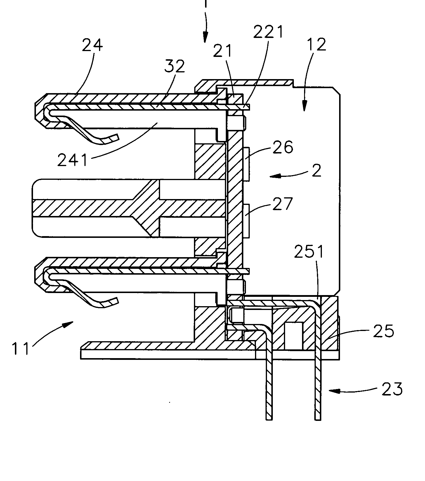
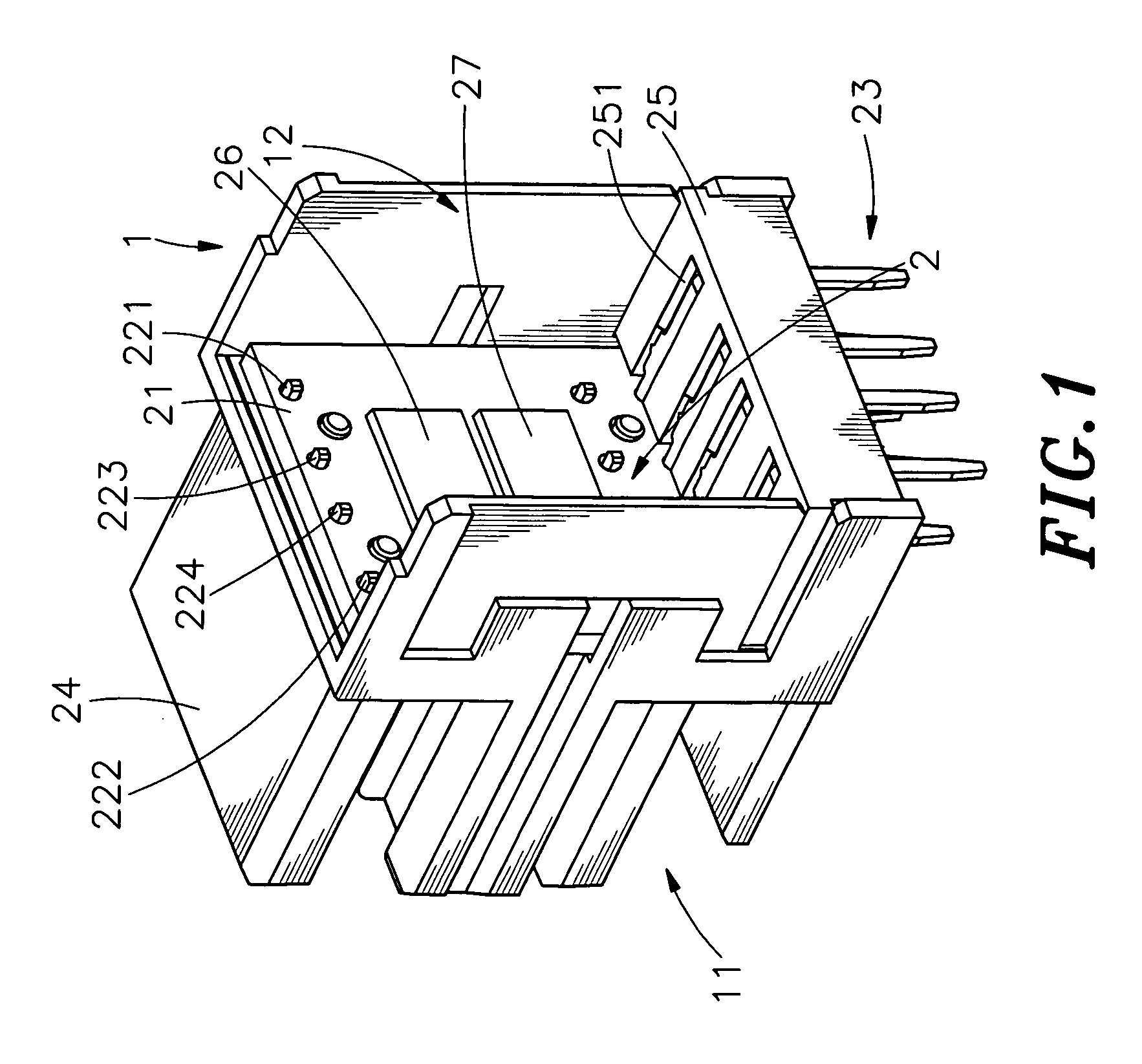
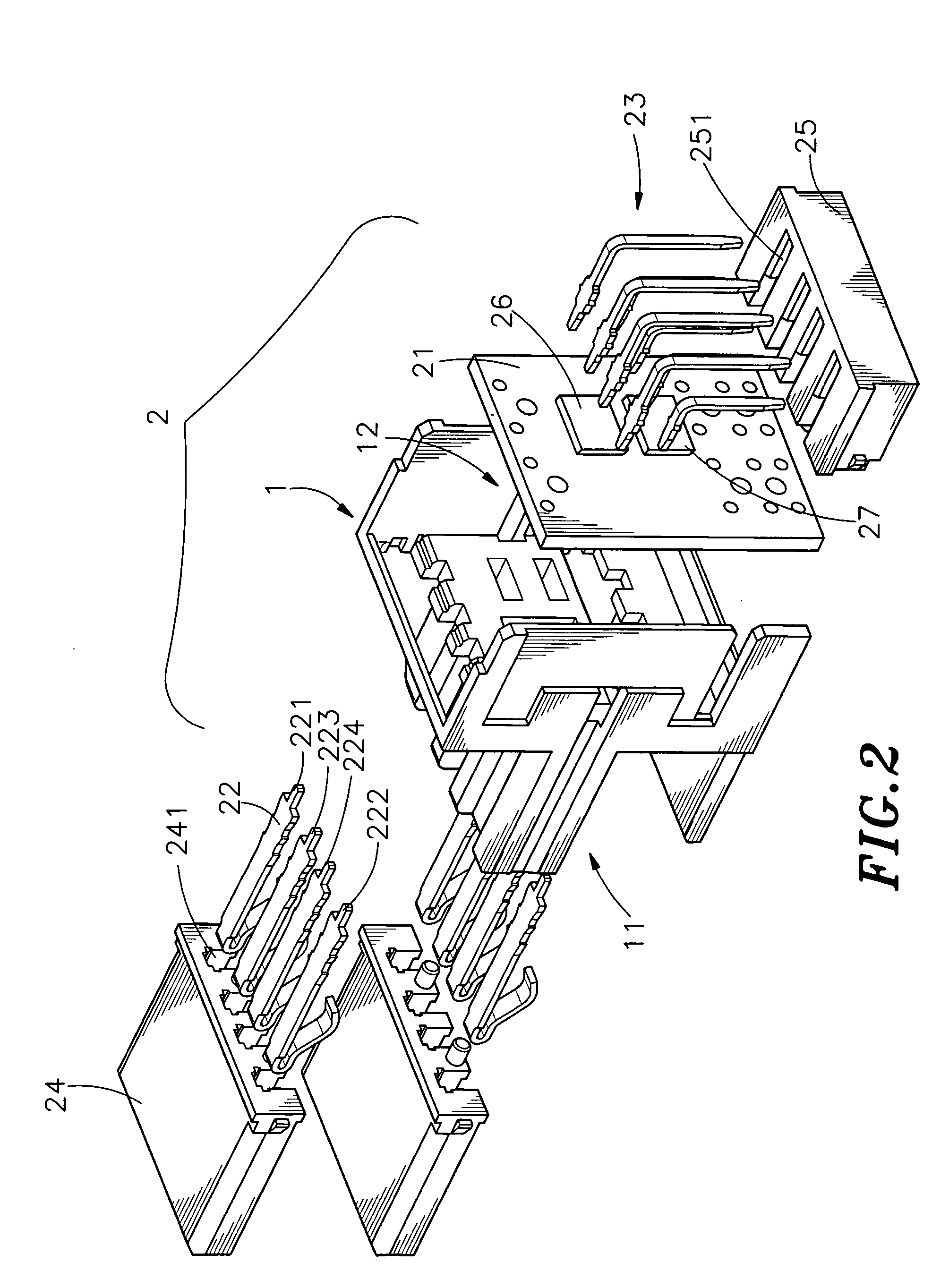
[0015] Referring to FIGS. 1, 2 and 3, the connector, according to an embodiment of the present invention, comprises an isolation chassis 1 and an electric module 2.

[0016] The isolation chassis 1 comprises a mating portion 11 on one side and a receiving space 12 on the other side thereof.

[0017] The electric module 2 comprises a plurality of interconnection-terminals 22 and a plurality of adaptor-terminals 23 extending from a built-in circuit board 21 outwardly. The interconnection-terminals 22 can be inlayed into slots 241 of an interconnection terminal set 24 and the adaptor-terminals 23 can be inlayed into slots 251 of an adaptor terminal set 25. Furthermore, please refer to FIG. 4, the built-in circuit boa...


PUM


Abstract

A structure of an USB connector comprising an isolation chassis and an electric module is provided. The circuit board a plurality of interconnection-terminals and a plurality of adaptor-terminals, wherein the power wave-filter module is positioned in a positive and negative power line of the circuit board and electrically connects to a first terminal and a fourth terminal of said interconnection-terminals and the signal wave-filter module is positioned in a signal line of the circuit board and electrically connects to a second terminal and a third terminal of the interconnection-terminals so as to cancel noise generated during signal transmission.

Description

BACKGROUND OF THE INVENTION [0001] 1. The Field of the Invention [0002] The present invention relates to a structure of connector, and more particularly, to an USB, Universal Serial Bus, connector having a built-in electrical module capable of reducing electromagnetic interference generated during signal and power transmission so as to meet high speed signal transmission requirement. [0003] 2. Description of Related Art [0004] With the recent rapid development of computer technology, high-tech products are highly developed and becoming highly popular nowadays. For transmitting information or using peripheral devices, interfaces are essential. The universal serial bus, namely USB, is a new generation of the interface for the computer peripheral devices, with several transmission speeds, such as 1.5 Mbps, 12 Mbps and 480 Mbps. Because the transmission speed of the USB is much faster than the parallel ports and the serial ports of the personal computer, therefore, applications of the U...

Claims


Application Information

Patent Timeline
Patent Type & Authority Applications(United States)
IPC IPC(8): H01R13/66H01R13/719
CPCH01R13/6625H01R12/716H01R31/065H01R13/6658
Inventor YU, CHIH CHING
Owner SPEED TECH
Why Eureka
Try Eureka