Method of ash removal from a biomass

a biomass and ash technology, applied in the field of biomass processing, can solve the problems of affecting the design, operation and performance of the combustor and the boiler, accelerating the metal wastage of the furnace and boiler components, and the impact of biomass ash on the performance of the flue gas cleaning equipment, so as to facilitate the addition of wash water, and facilitate the separation of mother liquor

Inactive Publication Date: 2012-01-12
PARABEL
View PDF11 Cites 19 Cited by
  • Summary
  • Abstract
  • Description
  • Claims
  • Application Information

AI Technical Summary

Benefits of technology

The invention includes several filters that help separate out different components during a chemical reaction involving biomass, alcohol, and a catalyst. These filters allow for better purification of the desired products by removing unwanted substances like salt or excessive acids. Additionally, there are also steps taken to adjust pH levels with added ammonia, resulting in improved efficiency of the overall process. A final step involves a drying procedure to produce a high-quality finished product. Overall, this technology helps create more pure and efficient biofuel production through an optimized separation and purification process.

Problems solved by technology

This patent discusses how to decrease the ash content in biomass to improve its quality for various uses like biofuel production. The problem arises from the natural inorganic substances that make up much of the plant's composition. These inorganics cause issues like fouling, corrosion, and reduced yields during thermal cracking. By reducing the ash content, it becomes easier to handle and convert the biomass into useful products without losing active ingredients. Various methods for doing so include using dilute acids, solvent extraction, and mechanical treatment.

Method used


Image

  • Method of ash removal from a biomass
  • Method of ash removal from a biomass
  • Method of ash removal from a biomass

Examples


example 1

Ash Reduction of Biocrude Fraction

[0089]A process of reducing ash content from biomass is described in this example. The process was tested by experiments.

[0090]Biomass was processed to extract proteins and obtain a biocrude fraction. The biocrude fraction included biomass after protein extraction. The biocrude fraction contained mostly carbohydrates and some protein.

[0091]Table 1 shows the ash content of the starting biocrude (labeled “Starting Ash”) and the ash content of the biocrude after treatment (labeled “Final Ash Treated”). In this example, anhydrous HCl and hydrous HCl were tested; 65° C. and 25° C. were tested. Table 1 shows that the initial biocrude contained about 20% ash, and the final ash content was reduced to about 5%.

TABLE 1Reductions in ash contentStartingFinal AshSampleHCLMethanolIncubationDurationAshTreatedBiocrudeAnhydrousRatio65° C.60 minutes20.3%8.5%(no water)3 wt / 1 wtHCL1NBiocrudeHCLRatio65° C.60 minutes20.3%8.3%(water)3 wt / 1 wt1NBiocrudeHCLRatio25° C.60+ mi...

example 2

Ash Reduction of Protein Fraction

[0092]A process of reducing ash content from biomass fraction is described in this example. The process was tested by experiments. After whole lemna biomass was treated for extraction of proteins, the protein fraction was further processed. The last row in Table 1 shows the ash content of the starting protein fraction and the ash content of the protein fraction after treatment.

[0093]Table 1 shows that the initial biocrude contained about 20% ash, and the final ash content was reduced to about 5% to 8%.

example 3

Biomass Growth and Processing System

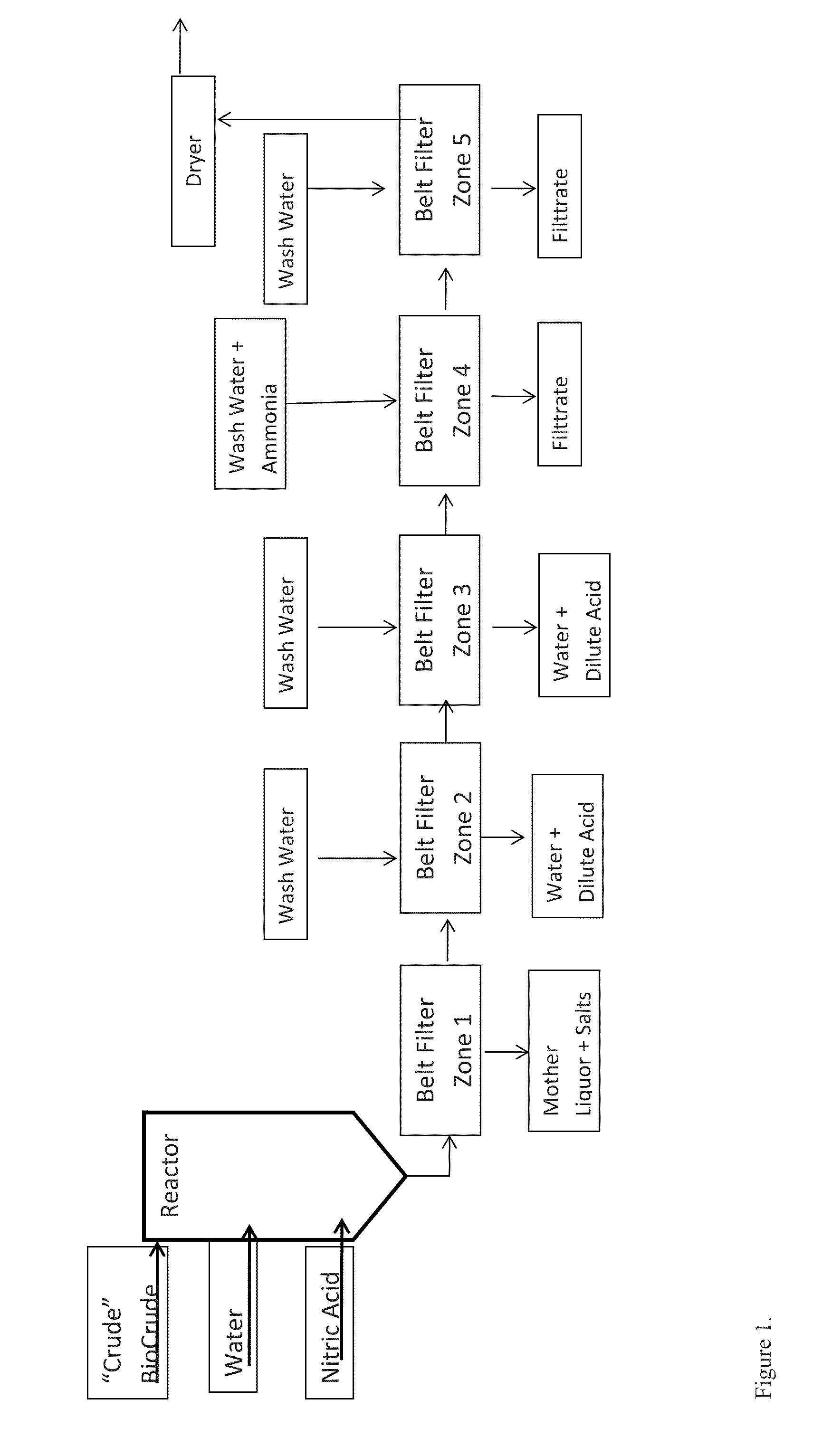
[0094]FIG. 1 shows an overview of the ash reduction system, which includes a co-counter current wash with neutralization process. Biocrude, water, and nitric acid are combined in a reactor. The reaction mixture enters the belt filter zone 1, from which the mother liquor and salts are removed. The remaining mixture is fed to the belt filter zone 2, and wash water is added to remove water and dilute acid. The washed mixture is fed to the belt filter zone 3, and wash water is added to remove water and dilute acid. The twice-washed mixture is fed to belt filter zone 4, and wash water and ammonia are added to remove the filtrate. The mixture is fed to belt filter zone 5, and wash water is added to removed more filtrate. The remaining mixture is fed to the dryer for further processing.

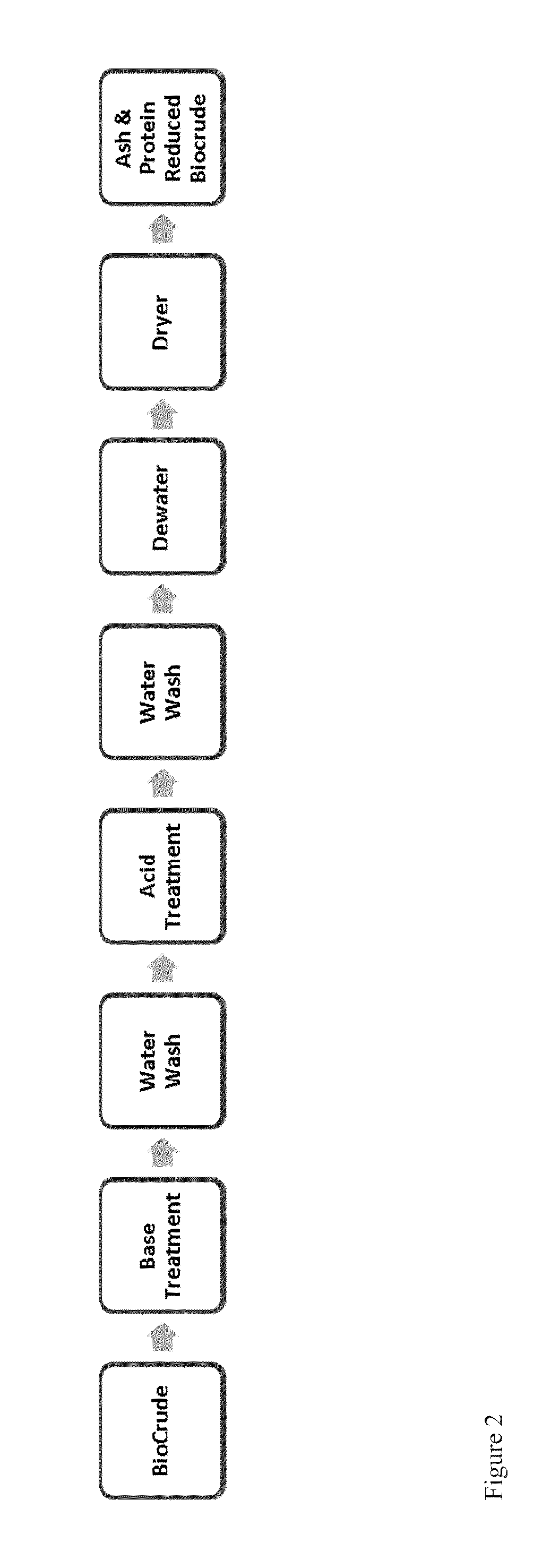
[0095]FIG. 2 shows an overview of the ash and protein reduction process from biocrude. The biocrude is treated with one or more bases. The mixture is washed with water, tr...


PUM

PropertyMeasurementUnit
Temperatureaaaaaaaaaa

Abstract

Disclosed herein is a process of reducing the ash content of a biomass feedstock or a biomass fraction. Embodiments include a process of reducing the ash content of a biomass feedstock or of a biomass fraction comprising: providing a biomass or biomass fraction; adding alcohol and acid to the biomass to yield a reaction mixture; separating the reaction mixture into a solid fraction and a liquid fraction by centrifugation; and distillating the liquid and collecting the solid to recover reaction reagents. The biomass can comprise aquatic species such as lemna.

Description


Claims


Application Information

Patent Timeline
Owner PARABEL
Why Eureka
Try Eureka