Carrier for a shaving device, comprising pairs of a cutting element and a hair lifting element

a shaving device and hair lifting technology, applied in the direction of metal working devices, etc., can solve the problem of reducing the effectiveness of the hair lifting process even further, and achieve the effect of optimizing the functioning of the hair lifting element and the cutting elemen

Active Publication Date: 2012-01-19
KONINKLIJKE PHILIPS ELECTRONICS NV
View PDF23 Cites 0 Cited by
  • Summary
  • Abstract
  • Description
  • Claims
  • Application Information

AI Technical Summary

Benefits of technology

[0012]During a manufacturing process of the carrier according to the present invention, the bent shape of a cutting element and / or a hair lifting element can easily be realized, namely by bending the element, which may be a metal element, in any known manner. The distance between the edge portion of a cutting element and the edge portion of a hair lifting element of one pair of elements can be chosen freely, which is another advantage of the present invention, as this distance is a critical parameter for optimizing the hair lifting process.
[0013]With two bending lines extending across a width of the element, the bent element has a stepped appearance. In particular, the bent element may have a shape that is comparable to the shape of a chair with a back, seat and front support. In such a case, it is sufficient if one of the elements is a bent element, wherein a space for allowing cut-off hair stubbles to escape is present between the front support of the chair-shape of the bent element and the other element, and wherein the back of the chair-shape may be resting on the other element.
[0014]With reference to the chair terminology used in the preceding paragraph, it is noted that the bent element may comprise three portions which are interconnected through the bending lines, namely a free end portion, which is the front support of the chair-shape, a connecting portion at a side where the element is attached, which is the back of the chair-shape, and an intermediate portion, which is the seat of the chair-shape, and wherein the intermediate portion has another orientation than the two other portions. With respect to the other portions, it is noted that an orientation of the free end portion of the bent element may be substantially the same as an orientation of the connecting portion of the element, but this is not necessary in the chair-shaped embodiment of the bent element.
[0015]An orientation of the connecting portion of the bent element may be substantially the same as an orientation of at least a portion of the other element. In that case, it is very well possible for the connecting portion of the bent element to be in gliding contact with the other element.
[0016]In one of many possible practical embodiments of the carrier according to the present invention, the hair lifting element is a bent element having a bent appearance with at least two bending lines, wherein each of the bending lines extends across a width of the hair lifting element. In such an embodiment, it may be that the hair lifting element is in gliding contact with the cutting element, at least at the position of one of the bending lines, wherein a bending line which is next, viewed from a side where the hair lifting element is attached to another element of the carrier to the edge portion of the hair lifting element, is located at a distance from the cutting element, and wherein all of a free end portion of the hair lifting element that extends from the latter bending line toward the edge portion of the hair lifting element is located at a distance from the cutting element. In this configuration, it is possible to have a space between the cutting element and the hair lifting element that is large enough for accommodating a cut-off hair stubble, so that such a stubble may escape instead of being in the way of the hair lifting element.
[0017]In the embodiment in which the hair lifting element is a bent element, the cutting element may be a straight element. Furthermore, it is possible for the free end portion of the hair lifting element to have a straight appearance as well. In that case, in order to realize optimal functioning of the hair lifting element and the cutting element, it is advantageous if the free end portion of the hair lifting element extends substantially parallel to the cutting element. A general advantage of having a straight appearance of the free portion of the hair lifting element is that the influence of wear on the functioning of the hair lifting element is kept to a minimum.

Problems solved by technology

When the construction of the pairs of elements is relatively heavy, there is a risk that the hair lifting elements cut through the hairs instead of lifting the hairs during a shaving process, which is another factor that leads to a less close shave on the basis of a decreased effectiveness of the hair lifting process.
Also, the higher the mass of the hair lifting elements, the more time it takes for these elements to move between the retracted position and the extended position, so that the effectiveness of the hair lifting process is decreased even further.

Method used


Image

  • Carrier for a shaving device, comprising pairs of a cutting element and a hair lifting element
  • Carrier for a shaving device, comprising pairs of a cutting element and a hair lifting element
  • Carrier for a shaving device, comprising pairs of a cutting element and a hair lifting element

Examples


first embodiment

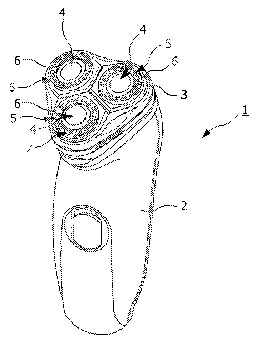
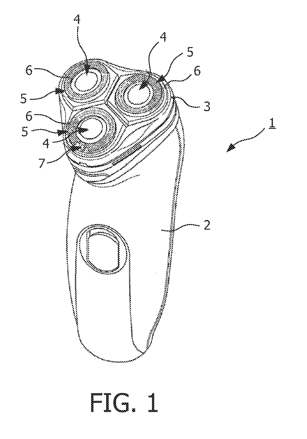
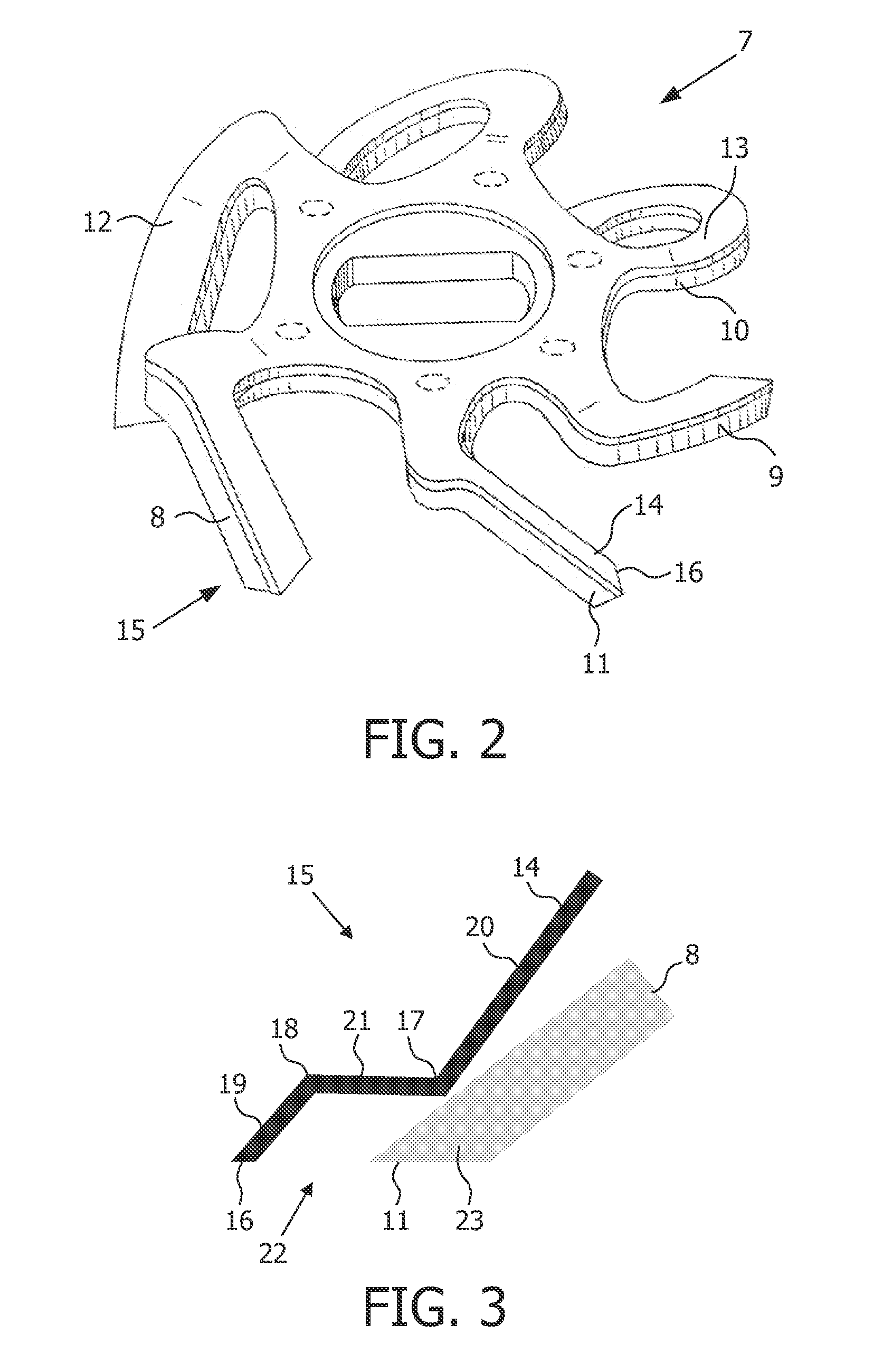
[0038]In principle, a shaving action can also be performed with the use of carriers 7 which are only equipped with cutting elements 8, wherein the hair lifting elements 14 are omitted. However, applying the hair lifting elements 14 leads to much better shaving results, as the hairs may be cut off at a level which is closer to the skin. The present invention is especially applicable in the field of carriers 7 having at least one pair 15 of a cutting element 8 and a hair lifting element 14, and will now be explained on the basis of FIGS. 3-8. In FIG. 3, a pair 15 of a cutting element 8 and a hair lifting element 14 according to the present invention is diagrammatically shown. In this embodiment, the hair lifting element 14 has a bent shape, wherein two bending lines 17, 18 are present in the hair lifting element 14, which extend across a width of the hair lifting element 14, substantially parallel to the outer edge 16. On the basis of the presence of the two bending lines 17, 18, thre...

second embodiment

[0046]The hair lifting element 14 does not necessarily need to be the element 8, 14 that is provided with bending lines 17, 18. In a second embodiment as shown in FIG. 5, the cutting element 8 has a bent appearance, whereas the hair lifting element 14 has a straight appearance. It is also possible that both elements 8, 14 are provided with two bending lines 17, 18, 26, 27, wherein, in a general sense, the shape of one of the elements 8, 14 is a mirror shape of another of the elements 8, 14. This possibility is shown in FIG. 6.

[0047]In the second embodiment as shown in FIG. 5, a connecting portion 28 of the cutting element 8 has an orientation that is substantially the same as an orientation of the hair lifting element 14. In this way, it is achieved that gliding contact of the hair lifting element 14 to the cutting element 8 is realized over a relatively large area. Nevertheless, an alternative to this configuration is also possible within the scope of the present invention, as can ...


PUM


Abstract

A carrier is adapted for use in a shaving device, and comprises at least one pair (15) of a cutting element (8) and a hair lifting element (14). At least one of the elements (8, 14) of the pair (15) has a bent shape, wherein the bent element (8, 14) is provided with at least two bending lines (17, 18). The bent shape of the at least one of the elements (8, 14) is such that in a functional arrangement of the elements (8, 14) with respect to each other, edge portions (11, 16) of the elements (8, 14) are located at a distance with respect to each other. Thus, a space (22) is present between the elements (8, 14) at the side of their edge portions (11, 16), which can be used for receiving cut-off hair stubbles which might otherwise hinder a movement of the hair lifting element (14).

Description

FIELD OF THE INVENTION[0001]The present invention relates to a carrier which is adapted for use in a shaving device, and which comprises at least one pair of elements, wherein one of the elements of the pair is adapted to function as a cutting element, wherein an edge portion of the cutting element is adapted to contact hairs and to perform a cutting action on hairs when being moved with respect to the hairs, and wherein another of the elements of the pair is adapted to function as a hair lifting element that is intended to precede the cutting element during a movement of the carrier, wherein an edge portion of the hair lifting element is adapted to engage hairs and lift hairs before the hairs are reached by the cutting element, and wherein the hair lifting element is movably arranged with respect to the cutting element.[0002]Furthermore, the present invention relates to a shaving device, comprising at least one carrier as mentioned, and means for driving the carrier such as to perf...

Claims


Application Information

Patent Timeline
Patent Type & Authority Applications(United States)
IPC IPC(8): B26B19/42
CPCB26B19/044B26B19/42B26B19/141
Inventor VAN DER VLIS, PETER HANSSLESAZECK, PAUL-RAINER VIKTOR KARLNIERS, GERTHOUBOLT, ERIK
Owner KONINKLIJKE PHILIPS ELECTRONICS NV
Why Eureka
Try Eureka