Metal melting system and metal melting process with annular hot gas insulation layer

A technology of thermal insulation layer and hot gas layer, applied in metal smelting equipment and technology, metal melting system and metal melting technology field, can solve the problems of reducing the quality excellent rate, increasing production cost, reducing production efficiency, etc., so as to improve melting efficiency and isolate Heat dissipation and crack reduction effect

Active Publication Date: 2021-03-30
湖南奥科新材料科技有限公司
View PDF8 Cites 0 Cited by
  • Summary
  • Abstract
  • Description
  • Claims
  • Application Information

AI Technical Summary

Problems solved by technology

[0003] Therefore, in summary, in the prior art, there are still many deficiencies such as poor heat preservation effect, difficult cleaning, short service life, etc. in the metal smelting process, which greatly increases the production cost and reduces the production efficiency, and also makes the The excellent rate of product quality is greatly reduced

Method used


Image

  • Metal melting system and metal melting process with annular hot gas insulation layer
  • Metal melting system and metal melting process with annular hot gas insulation layer
  • Metal melting system and metal melting process with annular hot gas insulation layer

Examples


Embodiment 1

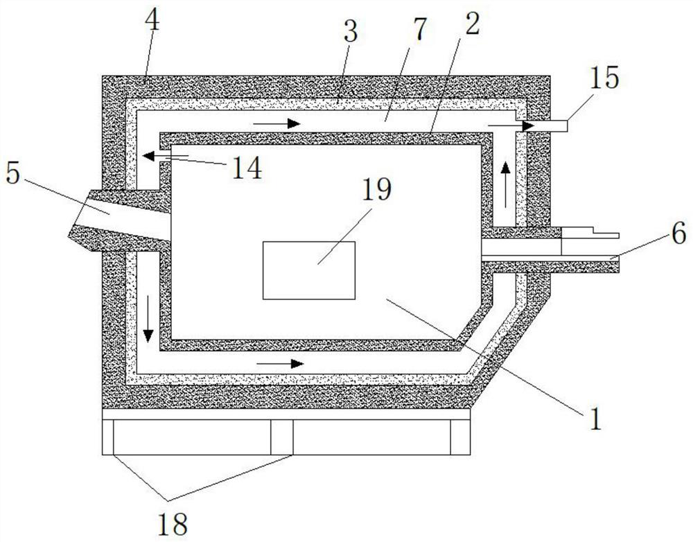
[0062] Such as figure 1 As shown, a metal melting system with an annular hot gas insulation layer, the system includes a melting furnace chamber 1, a furnace lining 2, an insulation layer 3, a furnace shell layer 4, a combustion device 5, a liquid outlet 6 and a feeding port 19. The cavity formed by the inner wall of the furnace lining 2 is the melting furnace cavity 1 . The outside of the furnace lining 2 is provided with an insulation layer 3 , and the outside of the insulation layer 3 is provided with a furnace shell 4 . The combustion device 5 passes through the furnace shell layer 4 , the insulation layer 3 , and the furnace lining 2 in sequence, and then communicates with the melting chamber 1 . The other side of the melting chamber 1 opposite to the combustion device 5 is provided with a liquid outlet 6 , and the liquid outlet 6 passes through the furnace lining 2 , the insulation layer 3 , and the furnace shell layer 4 sequentially and then communicates with the outsi...

Embodiment 2

[0064] Example 1 is repeated, except that the furnace lining 2 is integrally casted with refractory castables.

Embodiment 3

[0066] Repeat Example 2, the inner wall of the furnace lining 2 is painted with ZS-522 high temperature resistant self-cleaning non-stick coating (metal slag adhesion coating).


PUM

PropertyMeasurementUnit
thicknessaaaaaaaaaa
thicknessaaaaaaaaaa
angleaaaaaaaaaa

Abstract

The invention discloses a metal melting system with an annular hot gas heat preservation layer and a metal melting process. The system comprises a furnace lining, a melting furnace cavity formed by aninner cavity of the furnace lining, a heat preservation layer arranged outside the furnace lining, a furnace shell layer arranged outside the heat preservation layer, a combustion device arranged onthe side face of a furnace body, a liquid outlet, a feeding port and a heat preservation hot gas layer arranged between the heat preservation layer and the furnace lining. According to the system, after high-temperature hot flue gas generated by combustion in the hearth is led out, a new high-temperature flue gas heat preservation layer is formed outside the furnace lining, so the heat preservation effect can be greatly improved, loss of heat in the melting furnace cavity is reduced, the metal melting efficiency is improved, fuel consumption is reduced, meanwhile, the pressure in the melting furnace cavity can be well relieved, the temperature of the furnace body on the outermost side is reduced, and the production safety is improved.

Description

technical field [0001] The invention relates to metal smelting equipment and a process, in particular to a metal melting system and a metal melting process with an annular hot gas insulation layer, belonging to the technical field of metal processing. Background technique [0002] At present, in the metal smelting process, especially in the production process of fine spherical aluminum powder, it is necessary to use a melting furnace to melt the raw material aluminum ingot. 103. Furnace roof 104, chimney 105, special-shaped brick 107 for pouring liquid, metal feeding port 108, furnace door 109, etc., wherein the hearth is composed of standard refractory bricks 111 and insulation layer 110. Since the furnace is built with standard refractory bricks, there are gaps on the four sides of each brick in contact with the furnace, so the entire furnace is distributed with multiple horizontal and vertical gaps mixed with refractory mud. The gap area accounts for about 3-5% of the en...

Claims


Application Information

Patent Timeline
Patent Type & Authority Patents(China)
IPC IPC(8): F27B14/08F27B14/14F27D1/00F27D13/00F23L15/00F27D17/00
CPCF23L15/00F27B14/08F27B14/14F27B2014/002F27D1/0033F27D13/00F27D17/004Y02E20/34
Inventor 李代水李代权向文改
Owner 湖南奥科新材料科技有限公司
Why Eureka
Try Eureka