A kind of arch bridge type wave laying bridge and assembling method

An assembly method and technology for arch bridges, applied in electrical components and other directions, can solve the problems of increasing the amount of bridge material, increasing the construction cost of the bridge, and increasing the thickness of the steel plate of the bridge, so as to improve the stress mode, reduce the deformation, and increase the rigidity.

Active Publication Date: 2022-03-08
山东聚和新材料有限公司
View PDF8 Cites 0 Cited by
  • Summary
  • Abstract
  • Description
  • Claims
  • Application Information

AI Technical Summary

Problems solved by technology

The problem is that it is not safe, not beautiful, and not suitable for cable laying in buildings
When the site conditions require the bridge to increase the span, it is necessary to increase the amount of bridge materials, for example, to increase the thickness of the steel plate of the bridge, or to erect corresponding spanning measures such as bridge racks, suspension bridges, and truss bridges, which increases the construction cost of the bridge.

Method used


Image

  • A kind of arch bridge type wave laying bridge and assembling method
  • A kind of arch bridge type wave laying bridge and assembling method

Examples


Embodiment 1

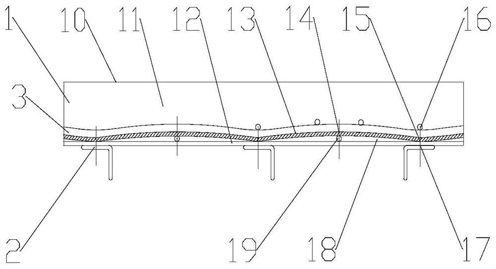
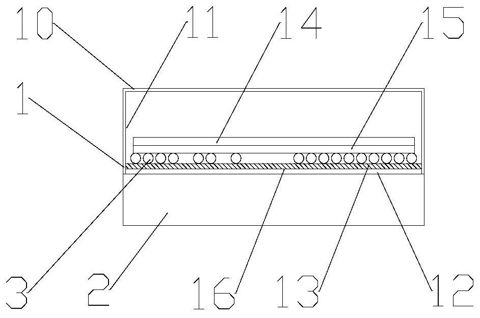
[0032] Such as figure 1 As mentioned above, the present embodiment discloses an arch bridge-type wave-laid cable bridge. The bridge structure mainly includes a shield assembly 1 arranged on the support arm 2 and a wave plate 13 arranged in the shield assembly. The shield assembly 1 is composed of a bottom plate 12, two side plates 11 and a cover plate 10 to form a rectangular frame, wherein the bottom plate 12 is a rectangular strip plate fixed on the support arm, wherein the position of the trough of the wave plate 13 is the same as that of the bottom plate 12 is also fixed on the support arm, and the position of the trough 15 is a load-bearing node, and the load-bearing node is placed on the support arm to form a node load-bearing structure; the node load-bearing structure bears the load formed by the weight of the cable 3 and the wave plate 13 itself. The crest 14 of the wave plate 13 is located between two adjacent brackets, so that the mechanical structure of the arch bri...

Embodiment 2

[0054] Other embodiments of the present disclosure also disclose another bridge-type cable bridge laid in a wave form. Unlike the cable bridge in Embodiment 1, the structure of the cable bridge does not have a bottom plate, and the wave plate 13 is directly fixed on the bracket by a clamp 19. Arm 2, or connected by binding, welding, riveting, welding, bolting, etc.

[0055] In the straight section of the wave plate, the horizontal thrust of the wave plate on the left and right sides of each support arm 2 can cancel each other out. The friction between them can offset part of the horizontal thrust. The wave plate 13 can be fixed with the support arm 2 to solve the problem of horizontal thrust. At bends or tees, etc., the supporting arms 2 are densely arranged, the span is smaller than the straight section, the amplitude is smaller than the straight section, and the horizontal thrust is smaller than the straight section. At bends or tees, etc., the overall rigidity of the brid...

Embodiment 3

[0058] In addition, the embodiment of the present disclosure also discloses the assembly method of the cable tray based on the above-mentioned arch bridge waveform laying, the method includes the following process reference figure 1 :

[0059] The corrugated board 13 has been pre-processed, and it is preferably processed and formed at the installation site of the bridge frame; first, the strip-shaped bottom plate 12 is laid on the support arm 2, flattened and fixed, and then one end of the strip-shaped corrugated board 13 is placed on the bottom plate 12 at the end. The supporting arms of the upper part are fixedly connected together at section 17, for example; the way of fixing the link includes welding, welding, riveting or bonding;

[0060] Then add support pillow 19 under the wave plate 13, under the premise of keeping the base plate 12 straight, make the wave plate 4 bend and deform, make it connect with the base plate 12 and the support arm at the adjacent support arm, f...


PUM


Abstract

The disclosure relates to an arch bridge-type wave-laying bridge and an assembly method, which belong to the technical field of power transmission and distribution and communication equipment. The bridge includes several brackets for supporting the bridge body, and also includes a wave plate bridge body arranged on the brackets The troughs of the wave slab bridge body are fixed on the support arms, and wave crests are arranged between adjacent troughs on the wave slab bridge body, and cables are fixed on the upper surface of the wave slab bridge body. By improving the mechanical structure of the existing cable bridge, the present disclosure can reduce the amount of materials and reduce the cost of the bridge under the condition of meeting the rigidity requirements of the bridge; span.

Description

technical field [0001] The disclosure belongs to the technical field of power transmission and distribution and communication equipment, and in particular relates to a bridge frame and an assembly method for arch-bridge waveform laying. Background technique [0002] The statements herein merely provide background information related to the present disclosure and do not necessarily constitute prior art. [0003] Cable trays are widely used in petrochemical, metallurgy, thermal power, electric power, machinery manufacturing, textile, transportation, construction, communication and other public facilities and civil facilities that use power and communication cables. [0004] The methods of cable laying include tower type, buried type, tunnel type, bridge type and other methods. Among them, the pole-tower type is the most common cable tray method, which is characterized in that the cables are laid on the poles and towers, and the power cables rely on their own strength and stif...

Claims


Application Information

Patent Timeline
Patent Type & Authority Patents(China)
IPC IPC(8): H02G3/04
CPCH02G3/0456
Inventor 马延春
Owner 山东聚和新材料有限公司
Why Eureka
Try Eureka