A vertical vibrating wheel with a built-in reversing mechanism

A reversing mechanism and vertical vibration technology, applied in the field of road rollers, can solve the problems of reduced load, unfavorable assembly and on-site maintenance, and heavy components, so as to reduce the difficulty of assembly and processing, facilitate and efficient on-site maintenance, and simplify the supporting structure.

Active Publication Date: 2017-01-18
XCMG CONSTR MACHINERY
View PDF1 Cites 0 Cited by
  • Summary
  • Abstract
  • Description
  • Claims
  • Application Information

AI Technical Summary

Problems solved by technology

[0005] However, the above scheme ignores the difficulty of assembly at first. The left eccentric shaft, middle eccentric shaft, four vibration bearings and four left vibration bearing seats are first assembled in the left vibrator housing, and then the components are assembled in the steel wheel housing. Heavy is a major difficulty when disassembling the vibrating wheel, which is not conducive to assembly and on-site maintenance
Similarly, the right exciter housing assembly has this problem, and "the gear case is positioned on the right vibrator bearing block and mounted on the end of the right exciter housing", making the whole assembly heavier and field assembly repairable become more difficult
Secondly, in fact, the centrifugal force generated by the rotation of the left eccentric shaft and the middle eccentric shaft needs to be transmitted through the left vibration bearing seat. Similarly, the centrifugal force generated by the rotation of the right eccentric shaft also needs to be transmitted through the right vibration shaft seat. In this way, the centrifugal force transmission route is complicated. , leading to low reliability of the overall structure
Furthermore, the patent intends to reduce the load of the vibration output bearing and improve the life of the vibration output bearing, but the improved vibration output bearing only reduces the load and does not fundamentally solve the problem of the use of the vibration output bearing

Method used


Image

  • A vertical vibrating wheel with a built-in reversing mechanism
  • A vertical vibrating wheel with a built-in reversing mechanism
  • A vertical vibrating wheel with a built-in reversing mechanism

Examples


Embodiment Construction

[0024] The present invention will be further described below in conjunction with drawings and embodiments.

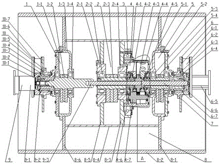
[0025] Such as figure 1 As shown, the present invention includes a vehicle frame, a pressure wheel 8, a left connection assembly 10 arranged inside the pressure wheel 8, a vibration drive assembly 9, a left vibration chamber 1, a middle vibration chamber 2, a gear box 4, a right vibration chamber 5 and a right vibration chamber. Connect the components6.

[0026]Wherein: the left vibration chamber 1 is mainly composed of a left housing 1-3, a left housing cover 1-1, a left vibrator 1-2 and a left vibration bearing 1-4. Among them, the left housing 1-3 and the left housing cover 1-1 form an independent chamber, which is fixedly connected to the pressure roller 8, and the left vibrator 1-2 provided inside it vibrates through the left vibration on both sides. The bearing 1-4 is vertically supported between the left housing cover 1-1 and the left housing 1-3. The right vi...


PUM


Abstract

The invention discloses a built-in vertical vibrating wheel for a reversing mechanism. The built-in vertical vibrating wheel comprises a vehicle frame and a pressing wheel (8), as well as vibration driving components (9), a left vibration chamber (1), an intermediate vibration chamber (2), a gearbox (4), a right vibration chamber (5) and right connecting components (6), which are arranged in the pressing wheel from left to right, wherein the left and right vibration chambers (1 and 5) adopt the structures of independent excitation chambers and fixed in the pressing wheel (8), so that the stressing mode of the vibration wheel is optimized, and the reliability of the vertical wheel is improved; the gearbox (4) is supported on the pressing wheel (8) through a pivoting support (3) and fixedly connected with the vehicle frame, so that the gearbox (4) does not rotate along with the pressing wheel (8), and the supporting structure of the gearbox (4) is greatly simplified.

Description

technical field [0001] The invention relates to a vertical vibrating wheel, in particular to a vertical vibrating wheel with a built-in reversing mechanism, which is suitable for road rollers. Background technique [0002] A road roller is a compacting device consisting of one or more metal cylindrical rollers or rubber tires, which can crush rock, compacted soil, asphalt concrete or gravel by the rolling and / or vibration of the compacting device. The most widely used vibration method in the road roller market is circular vibration, that is, the exciter arranged along the axis of the vibrating wheel rotates periodically to form a periodic centrifugal force. [0003] The disturbance of the circular vibrating wheel in the horizontal direction will cause the peeling of the surface material, while the theoretical horizontal vibration displacement of the vertical vibration is zero, which is conducive to improving the compaction quality of the laminated surface. For circular vibr...

Claims


Application Information

Patent Timeline
Patent Type & Authority Patents(China)
IPC IPC(8): E01C19/28
CPCE01C19/286
Inventor 周保刚夏磐夫牛春亮刘邦辉江奎峰林栋冰谢娟娟
Owner XCMG CONSTR MACHINERY
Why Eureka
Try Eureka