Fenestration system with solar cells

a technology of solar cells and fenestration systems, which is applied in the direction of photovoltaic supports, special door/window arrangements, door/window protective devices, etc., can solve the problems of reducing the interior daylight quality and the potential for electric lighting energy savings, reducing the daylight utilization rate, and not exploiting the full potential for energy, so as to improve daylight utilization rate, save energy, and save energy.

Inactive Publication Date: 2012-01-19
SINVENT AS
View PDF5 Cites 47 Cited by
  • Summary
  • Abstract
  • Description
  • Claims
  • Application Information

AI Technical Summary

Benefits of technology

[0032]The fenestration system may typically be positioned above eye height. In this position direct sunlight redirected in a direction above the horizontal plane will not cause glare for the building occupant.
[0033]The proposed system has the potential to provide significantly higher energy savings than all systems on the market today, and also attends to the need for visual contact through the window opening.
[0034]Traditional shading solutions without solar cells include dark exterior blinds or white/grey interior blinds. Compared to such solutions, the fenestration system according to the present invention can save energy both from improved daylight utilization (reduced electric lighting load

Problems solved by technology

Windows are also associated with negative factors such as heat loss, glare and unwanted solar heat.
In addition, the spatial distribution of the admitted daylight is often very uneven, reducing the interior daylight quality and the potential for electric lighting energy savings.
Today's solutions for daylight redirection systems and solar windows do not exploit the full potential for energy savings and most solutions offered to the market put significant limitations on the visual contact through the window opening.
However, a serious shortcoming of daylight redirection systems on the market today is that these systems only provide energy savings at times when daylight is needed, i.e. when the space is occupied by people.
Also, many of the daylight redirection systems in the market significantly reduce the visual contact with the exterior.
Also, since the productio

Method used


Image

  • Fenestration system with solar cells
  • Fenestration system with solar cells
  • Fenestration system with solar cells

Examples


Embodiment Construction

[0050]Example embodiments of the fenestration system will now be explained with reference to the drawings. The same reference numerals indicate the same elements throughout all the drawings.

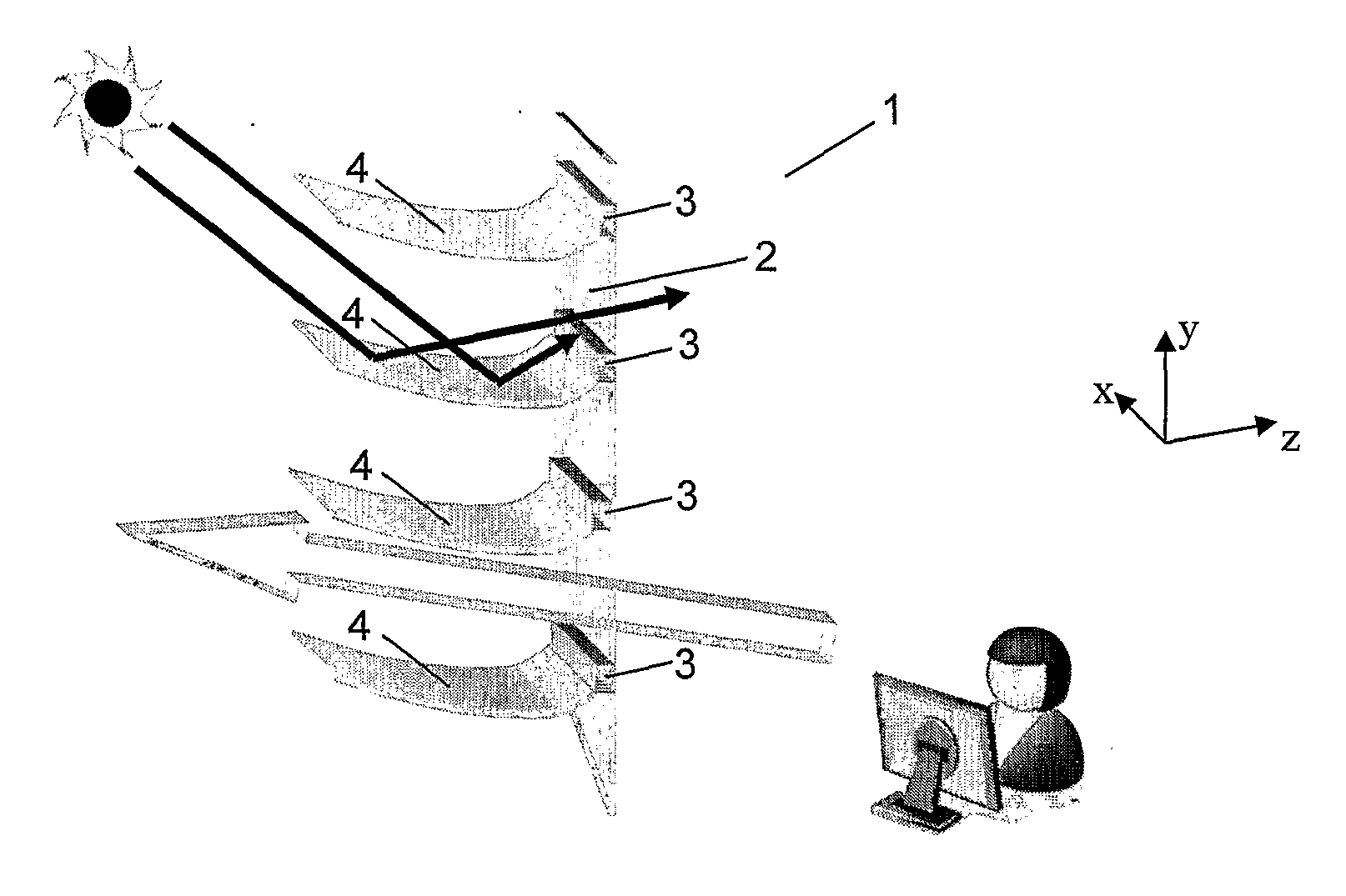
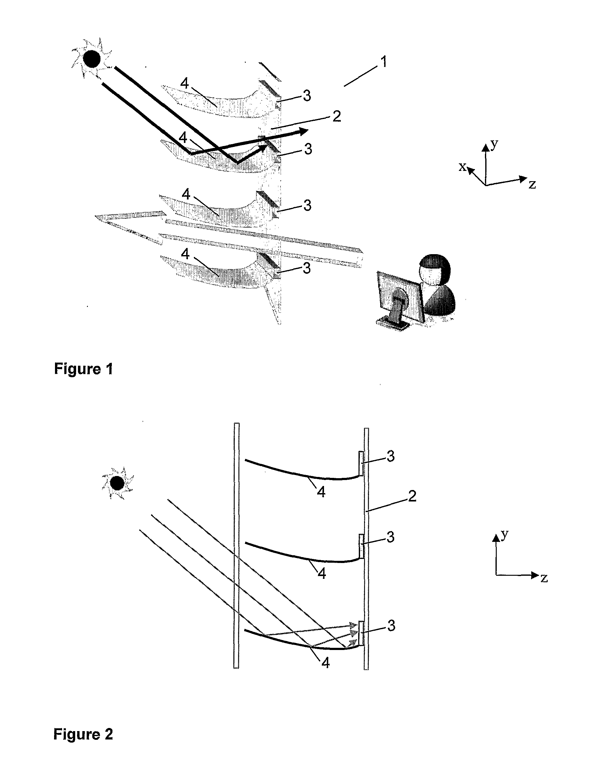
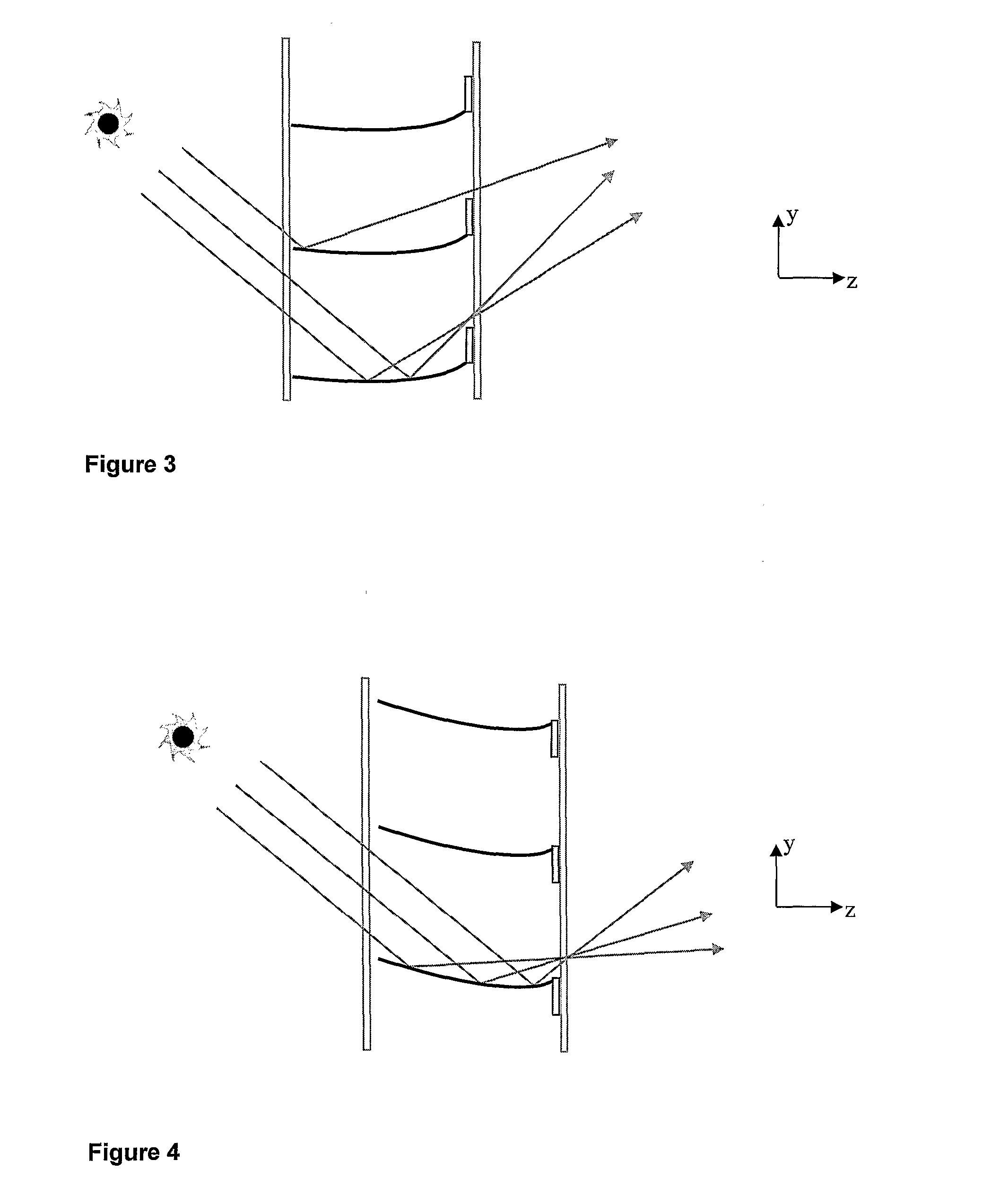
[0051]An embodiment of the new fenestration system 1 is shown in FIG. 1. The fenestration system comprises daylight redirecting blinds 4 and a stripe pattern of solar cells 3 attached to a window pane 2. As may be seen from FIG. 1, direct sunlight is concentrated onto the stripe pattern of solar cells by the redirecting blinds, but at the same time direct sunlight (and / or diffuse daylight) is redirected by the blinds through the window pane for improved daylight distribution within an interior space, e.g. inside a building. At the same time occupants inside the building will have good viewing conditions out of the window without being exposed to glare from direct sunlight or glare from redirected sunlight (provided that the fenestration system is located above eye height).

[0052]Although FIG. 1 sh...


PUM


Abstract

It is described a fenestration system comprising a window pane provided with a horizontal stripe pattern of solar cells, and window blinds provided with slats operative to concentrate direct sunlight onto said solar cells and operative to redirect diffuse daylight and/or direct sunlight for improved daylight distribution within an interior space. The fenestration system may be provided with control means for automatically adjustment of said window blinds based on a number of parameters like sun position, sky conditions, energy demands, need for daylight within the interior space and need for solar shading.

Description

INTRODUCTION[0001]The present invention concerns a fenestration system, especially for electrical energy production, daylight redirection and solar shading.BACKGROUND[0002]Building occupants regard windows as highly important building elements. The main attributes of window openings are to enable a visual contact with the exterior surroundings and to admit daylight into the building interiors. Windows allow the building occupant an outward view and enable the occupant to keep track of changes in weather and daylight conditions.[0003]Windows are also associated with negative factors such as heat loss, glare and unwanted solar heat. In addition, the spatial distribution of the admitted daylight is often very uneven, reducing the interior daylight quality and the potential for electric lighting energy savings.[0004]In recent years there has been a trend towards the use of more glass in commercial buildings. Buildings with glass facades often require advanced fenestration systems with o...

Claims


Application Information

Patent Timeline
IPC IPC(8): E06B7/28E06B7/00
CPCE06B9/264E06B2009/2417H01L31/0547E06B2009/2643Y02E10/52E06B2009/2476Y02B10/10
Inventor KOLAS, TOREFAGERBERG, RAGNARJOHNSEN, LARS
Owner SINVENT AS
Why Eureka
Try Eureka