Supercharge Your Innovation With Domain-Expert AI Agents!

Circuit board

a technology of circuit boards and printed boards, applied in the field of circuit boards, can solve the problems of possible disconnection between the electronic component b>700/b> and the printed board b>800/b>, and the likelihood of being detached from the printed wiring

Active Publication Date: 2012-01-19
MURATA MFG CO LTD
View PDF66 Cites 9 Cited by
  • Summary
  • Abstract
  • Description
  • Claims
  • Application Information

AI Technical Summary

Benefits of technology

The present invention provides a circuit board that prevents an electronic component from being detached from the circuit board. This is achieved by designing the circuit board with a laminated body made of flexible insulating layers, with internal conductors overlaid on a first external electrode and not connected to each other through via hole conductors. This prevents the electronic component from being easily detached from the circuit board.

Problems solved by technology

Meanwhile, the conventional circuit board 500 has a problem in that it is likely to be detached from the printed wiring board 600.
However, in a case in which the printed board 800 is attached to a casing by an adhesive or other material, the problem of possible disconnection between the electronic component 700 and the printed board 800 may also occur.

Method used


Image

  • Circuit board
  • Circuit board
  • Circuit board

Examples


Embodiment Construction

[0028]In the following, a circuit board according to preferred embodiments of the present invention will be described with reference to the drawings.

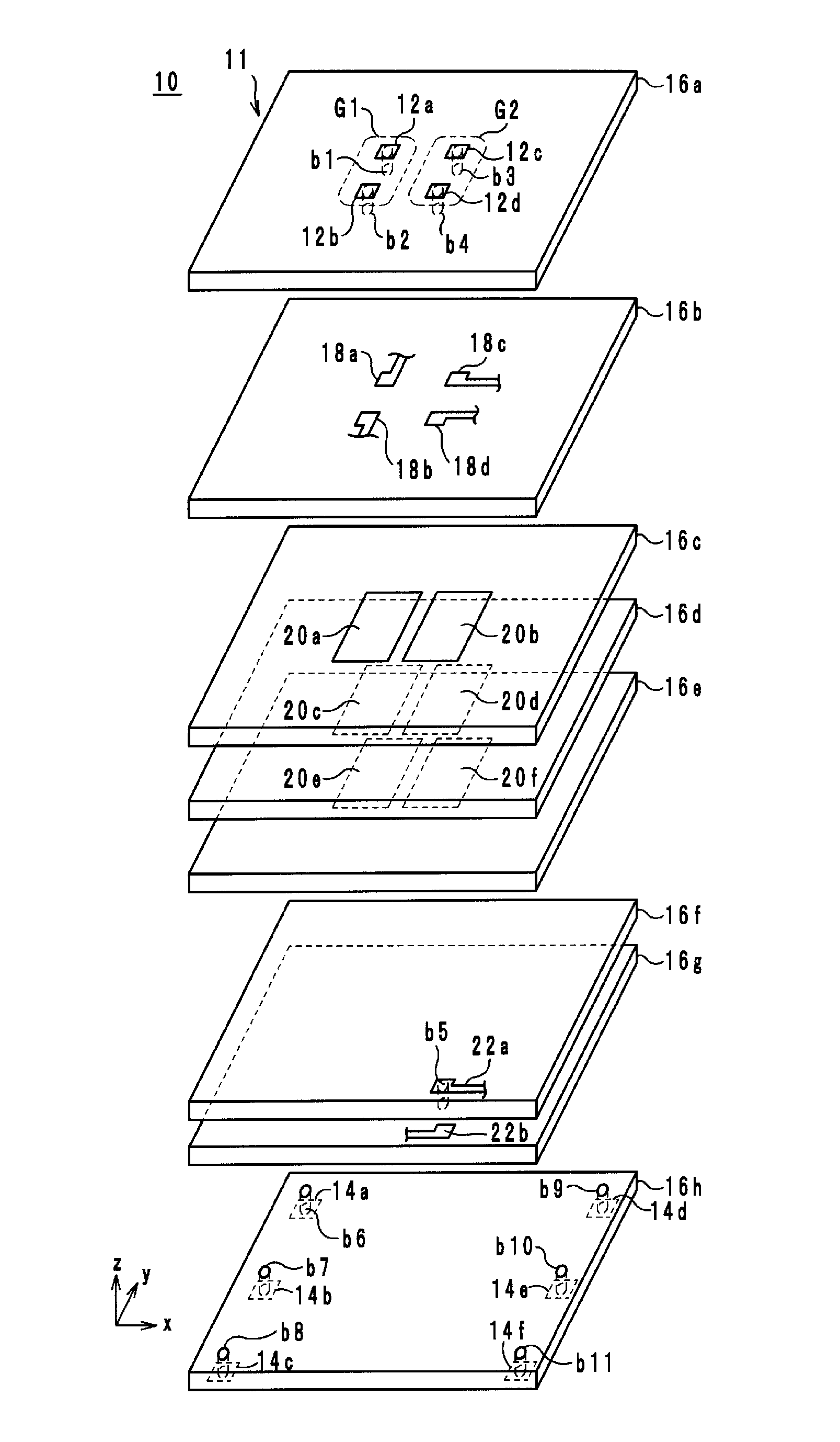
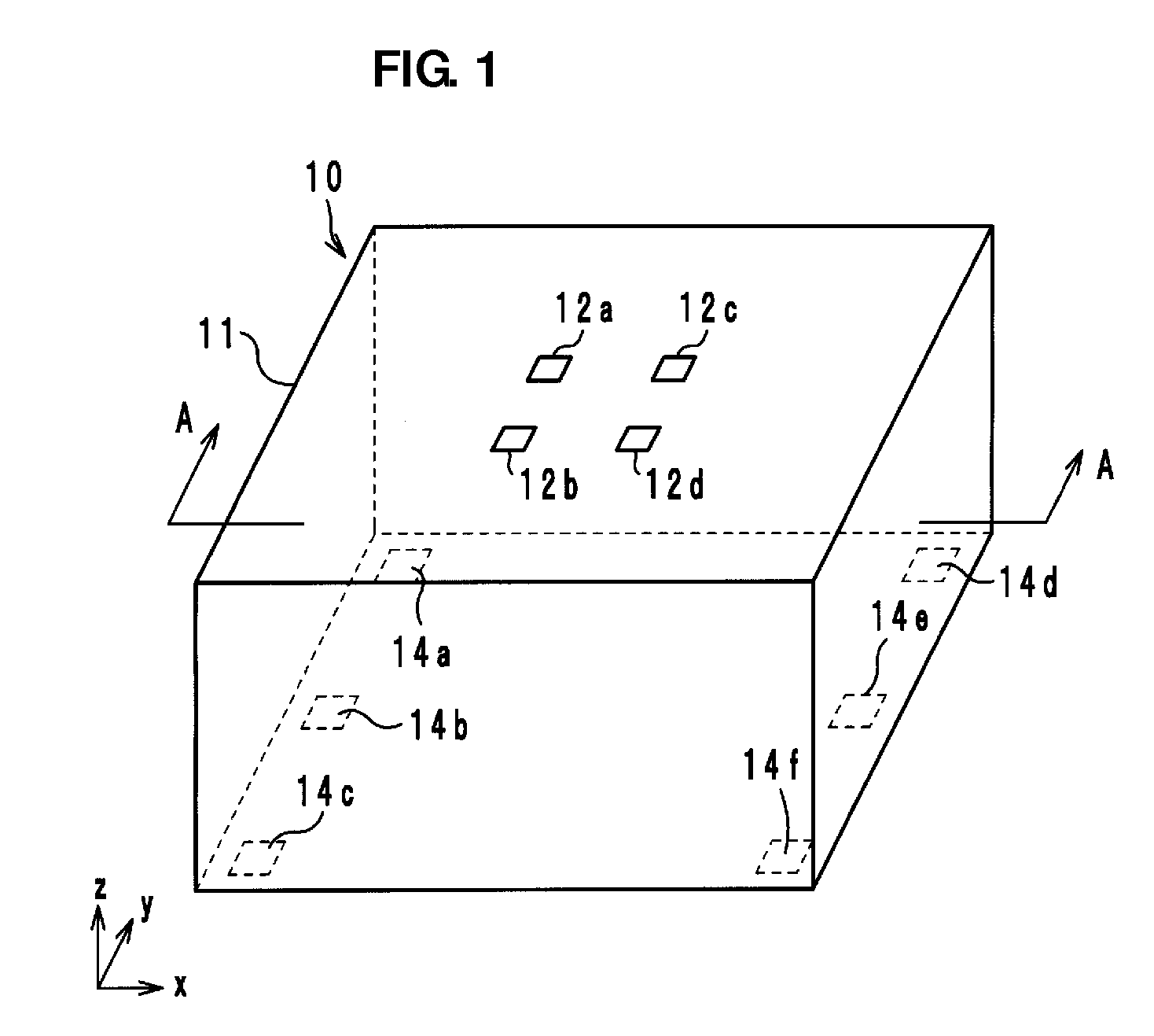
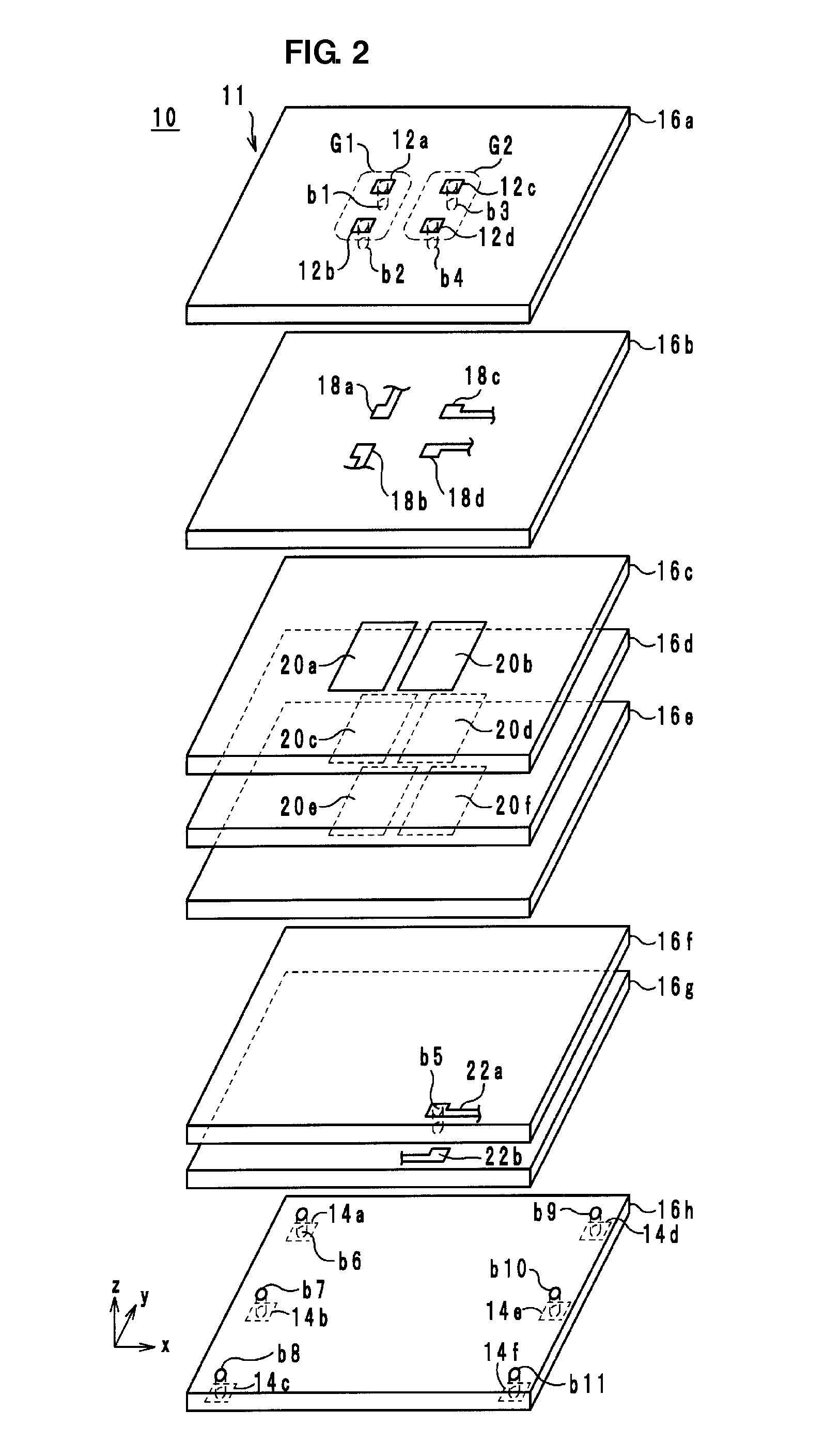
[0029]In the following, a configuration of a circuit board according to preferred embodiments of the present invention will be described with reference to the drawings. FIG. 1 is an external perspective view of a circuit board 10 according to a preferred embodiment of the present invention. FIG. 2 is an exploded perspective view of the circuit board 10 in FIG. 1. FIG. 3 is a cross-sectional structural view of the circuit board 10 in FIG. 1 which is taken along line A-A. FIG. 4 is a perspective view from a lamination direction of the circuit board 10 in FIG. 1. In FIGS. 1 to 4, a lamination direction is defined as a direction in which insulating-material layers are laminated during fabrication of the circuit board 10. The lamination direction is referred to as a z-axis direction. A direction along the long sides of the circuit board 10 i...


PUM

PropertyMeasurementUnit
flexibleaaaaaaaaaa
areaaaaaaaaaaa
stressaaaaaaaaaa

Abstract

A circuit board includes a laminated body including a laminate of a plurality of insulating-material layers made of a flexible material. External electrodes are provided on the top surface of the laminated body. An electronic component is mounted on the external electrodes. A plurality of internal conductors, when viewed in plan in the z-axis direction, are overlaid on the external electrodes and are not connected to one another in regions in which the internal conductors are overlaid on the external electrodes.

Description

BACKGROUND OF THE INVENTION[0001]1. Field of the Invention[0002]The present invention relates to circuit boards, and more particularly, to a circuit board on which an electronic component is to be mounted.[0003]2. Description of the Related Art[0004]Circuit boards including laminates of ceramic layers are known as conventional general circuit boards. FIG. 10 is a diagram illustrating a conventional circuit board 500 mounted on a printed wiring board 600. In addition, an electronic component 700 is mounted on the circuit board 500.As illustrated in FIG. 10, the circuit board 500 is composed of a main body 501 and external electrodes 502 and 503. The main body 501 is composed of a laminate of ceramic layers and is a rigid board. The external electrodes 502 and 503 are provided on a top surface and a bottom surface, respectively, of the main body 501.[0005]The printed wiring board 600 is a motherboard mounted on, for example, an electronic device, such as a mobile phone, and is provide...

Claims


Application Information

Patent Timeline
Patent Type & Authority Applications(United States)
IPC IPC(8): H05K1/00
CPCH01L23/49822H05K1/0271H05K1/141H05K1/16H05K3/4632H01L2224/16225H05K2201/0352H05K2201/09672H05K2201/10674H01L2224/16227H01L2924/15311H05K2201/0129H01L2224/05568H01L2224/05573H01L2924/00014H01L2224/05599H01L23/12H01L23/14H05K3/46H05K1/115
Inventor KATO, NOBORU
Owner MURATA MFG CO LTD
Features
  • R&D
  • Intellectual Property
  • Life Sciences
  • Materials
  • Tech Scout
  • Unparalleled Data Quality
  • Higher Quality Content
  • 60% Fewer Hallucinations
Learn More