Steering head

a steering head and head technology, applied in the direction of drilling casings, drilling pipes, directional drilling, etc., can solve the problems of reducing the efficiency of operation and maneuverability of these steering heads, the inability to adjust the position of the steering head along a horizontal axis in these prior art steering heads, and the limited amount of vertical adjustmen

Active Publication Date: 2012-01-19
VERMEER MFG CO
View PDF3 Cites 3 Cited by
  • Summary
  • Abstract
  • Description
  • Claims
  • Application Information

AI Technical Summary

Benefits of technology

[0009]The steering head is innovative in that the powered actuator may be mounted to the first flap face of the steering flap and the body surface of the steering head's body. When operative, the powered actuator may extend the first flap face into the extended position, thereby enabling the steering head to change the direction of its cutting path. In the extended position, the steering flap will encounter frictional resistance forces with the soil wall, thereby causing the lead edge of the steering head to move in a direction opposing the extended steering flap. For example, if a steering flap on the right side of the steering head is extended, the lead edge of the steering head will tend to move in a direction toward the left through the soil. These same frictional resistance forces will cause the lead edge of the steering to tend to move in an upward direction in the soil with a steering flap extended on the bottom of the steering head. Once the desired alignment has been achieved, the powered actuator may then be deactivated. This in turn uniquely enables the biased hinge at the hinge end of the steering flap to automatically retract the steering flap into a completely closed position by operation of the spring action of the biased hinge with the assistance of the frictional impact forces of the soil wall pushing on the steering flap. This configuration uniquely allows the steering head to be more maneuverable and therefore easier to steer through a desired cutting path in the soil, along both vertical and longitudinal axes. The steering head is therefore able to operate more efficiently, thereby reducing the amount of time spent and power consumed in the boring operation on a project. Furthermore, as the steering flap may be automatically closed at the hinge end by the biased hinge, the steering flap may be less likely to be deformed or allow soil to enter the steering head underneath a steering flap in the extended position. Accordingly, the steering flap may not sustain damage as frequently during the boring operation and its longevity may therefore be increased.
[0014]As discussed above, this configuration uniquely enables the steering head to be more maneuverable in soil and therefore more efficient in its boring operation. The plurality of steering flaps may enable an efficient change of direction of the steering head toward the desired cutting path. For example, if a steering flap on the right side of the steering head is extended, a steering head on the left side of the steering head may be retracted, thereby steering the lead edge of the steering head toward the left. Likewise, these same frictional resistance forces will cause the lead edge of the steering to tend to move in an upward direction in the soil with a steering flap extended on the bottom of the steering head and retracted on the top of the steering head. With the deactivation of the powered actuator on a steering flap, the configuration of the spring action on the biased hinge of each deactivated steering flap uniquely enables these steering flaps to uniformly retract with the assistance of the frictional impact forces of the soil wall on the steering flaps. This configuration may therefore improve the efficiency of the boring operation and the longevity of the steering head.
[0021]The combination of an altitude sensor and one or more positional sensors may uniquely enable the steering head to be accurately positioned in the desired cutting path of the soil, along vertical and horizontal axes. The information gathered by the altitude sensor and the positional sensors may therefore indicate when one or more of the steering flaps should be extended or retracted, depending on the position of the steering head in reference to the desired cutting path.
[0023]In another embodiment of the present invention, the steering head may further include one or more shields laterally disposed on the first flap face of the steering flap adjacent to the outer tube. The shields may be operative to prevent soil from entering beneath the steering flap in the extended position and to provide support to the steering flap. In another embodiment, a center rib may be disposed proximate to the shields operative to provide additional support to the steering flap.

Problems solved by technology

However, the position of the steering head along a horizontal axis could not be adjusted in these prior art steering heads.
Furthermore, the amount of vertical adjustment was limited by the amount of torsion that could be applied to the nut and bolt configuration Other prior art steering heads utilized projections allowing some adjustment of the direction of the steering head along both vertical and horizontal axes.
As a result, the frictional and impact forces between the projections and the surrounding soil wall as well as the penetration of soil under these projections reduced the efficiency of operation and maneuverability of these steering heads.
This resulted in increased labor and utility costs budgeted for a project.
Furthermore, it is understood that the repeated impact between the steering head projections and the soil wall deformed these projections, thereby damaging the steering head and reducing its operational efficiency, resulting in added equipment and repair costs.
In order to partially offset the occurrence of deformation, it is understood that these prior art steering head projections could be partially closed manually, a process that again reduced the efficiency of the boring operation.

Method used


Image

  • Steering head
  • Steering head
  • Steering head

Examples


Embodiment Construction

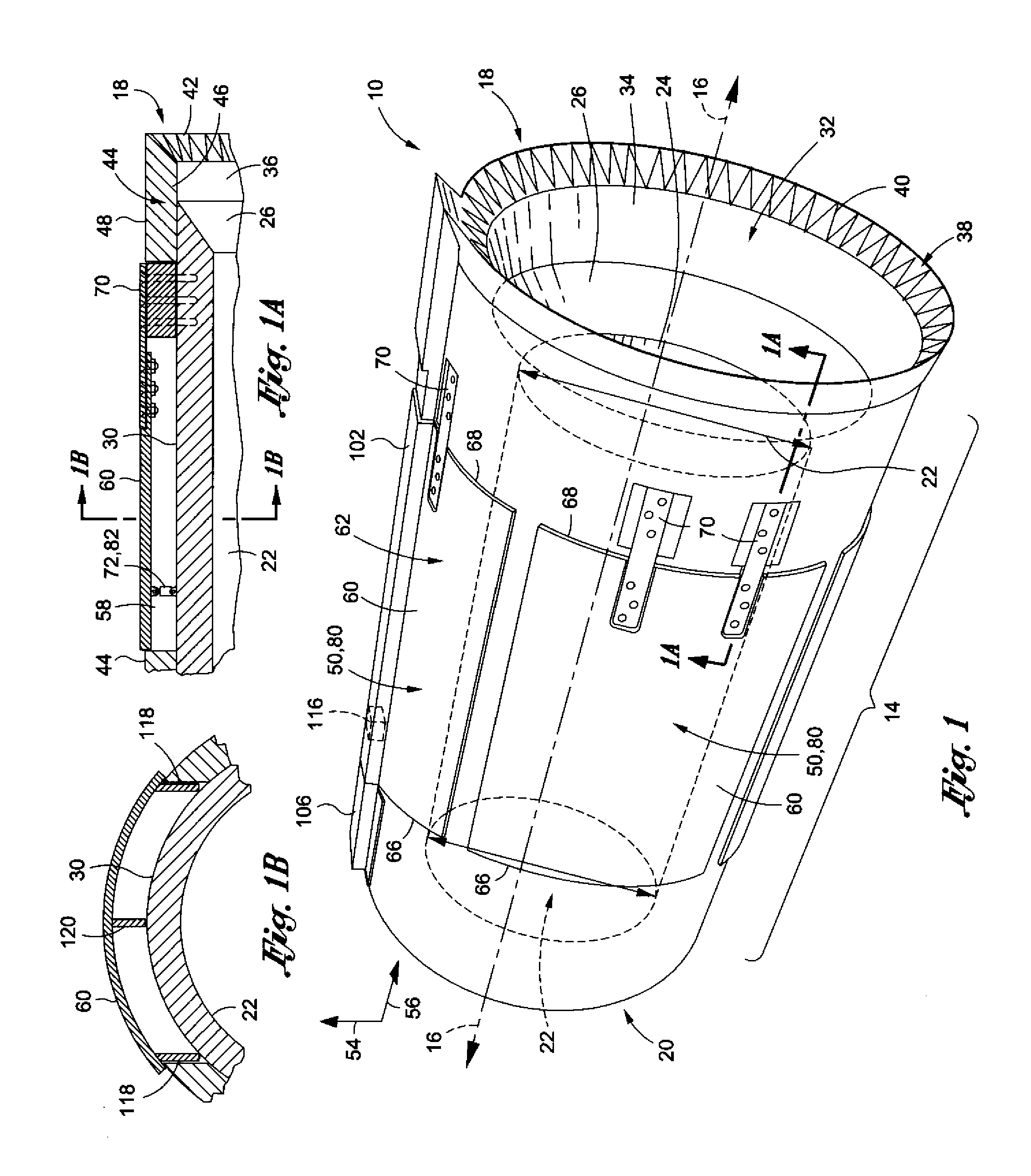
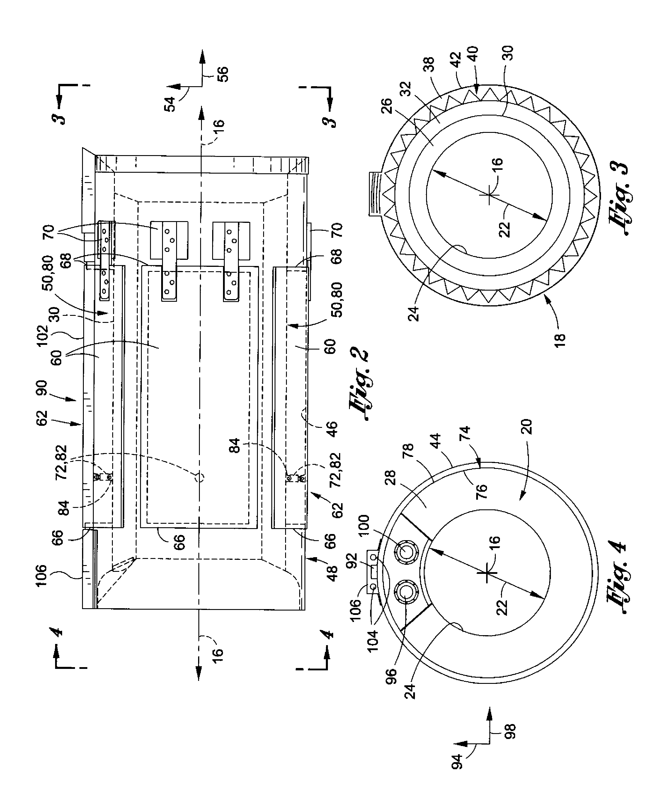
[0033]The drawings referred to herein are for the purposes of illustrating the preferred embodiments of the present invention and not for the purposes of limiting the same.

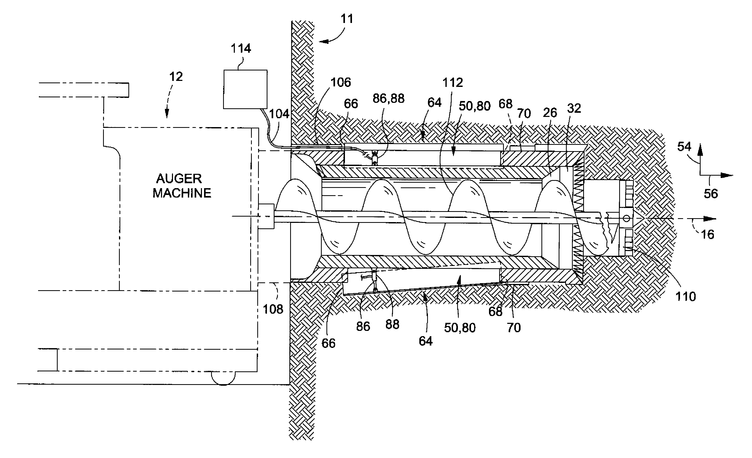
[0034]FIGS. 1 and 2 are an embodiment of the steering head 10 having a generally cylindrical body 14 defining a longitudinal body axis 16. The body 14 may have a first body end 18 and an opposing second body end 20. The second body end 20 of the steering head 10 may be mounted to a casing 108 as depicted in FIG. 6, preferably by welding. As shown in FIG. 6, the casing 108 is also engaged to an auger machine 12, with an auger unit 112 engaged to and extending from the auger machine 12 through the casing and the steering head 10. The auger unit 112 may be equipped with a drill bit 110 for cutting through various types of soil 11, from running sand to round rock. The auger machine 12 rotates the auger unit 112, thereby enabling the auger unit 112 to perform a boring or tunneling operation through the surrounding soil...


PUM


Abstract

A steering head for use with a casing, the steering head having a generally cylindrical body with a first body end with a lead edge, a second body end with a rear edge, and a body surface extending from the lead edge to the rear edge, an outer tube with an internal side generally facing the body surface, the outer tube extending from the first body end to the second body end, and a steering flap disposed on an external side of the outer tube having a first flap face facing radially inwardly and a second flap face facing radially outwardly. A biased hinge is secured to both the outer tube and the steering flap, the biased hinge being operative to retract the steering flap into a retracted position from an extending position.

Description

CLAIM OF PRIORITY[0001]This application is a continuation of U.S. patent application Ser. No. 12 / 433,587 filed Apr. 30, 2009, the entire disclosure of which is incorporated by reference herein.STATEMENT RE: FEDERALLY SPONSORED RESEARCH / DEVELOPMENT[0002]Not applicableBACKGROUND[0003]The present invention relates generally to a steering head for use with an auger for boring through soil.[0004]Underground dredging and boring operations are necessary for the laying of underground utility lines (e.g. water, sewer, and power). The boring or tunneling of the soil to clear a path for such underground utility lines requires the use of a steering head, a casing, an auger unit, and an auger machine The casing is typically weldably mounted to the steering head at one end and engaged to the auger machine at the opposite end, with an auger unit extending from the auger machine through the casing and into the steering head. The auger machine rotates the auger, thereby enabling the auger unit to pe...

Claims


Application Information

Patent Timeline
Patent Type & Authority Applications(United States)
IPC IPC(8): E21B7/08
CPCE21B7/201E21B7/062E21B7/046
Inventor MALCOLM, WILLIAM
Owner VERMEER MFG CO
Why Eureka
Try Eureka