Light guide plate and backlight unit including the same

a technology of backlight unit and guide plate, which is applied in the direction of lighting device details, lighting and heating apparatus, instruments, etc., can solve the problems of generating a dark zone, unsuitable for high brightness display, and the number of light sources being able to loca

Inactive Publication Date: 2012-01-19
LG DISPLAY CO LTD
View PDF14 Cites 28 Cited by
  • Summary
  • Abstract
  • Description
  • Claims
  • Application Information

AI Technical Summary

Benefits of technology

[0015]An object of the present invention is to provide a light guide plate

Problems solved by technology

A liquid crystal display device including the edge type backlight unit may have a slim profile owing to arrangement of the light source in a non display region, but may be unsuitable for high brightness display because the number of light sources been capable of locating in the non display region, is limited.
This makes it impossible for the light guide plate to uniformly emit light from the entire surface thereof, and the partial region of the light guide plate may be brighter or

Method used


Image

  • Light guide plate and backlight unit including the same
  • Light guide plate and backlight unit including the same
  • Light guide plate and backlight unit including the same

Examples


Embodiment Construction

[0031]Reference will now be made in detail to the preferred embodiments of the present invention, examples of which are illustrated in the accompanying drawings. Wherever possible, the same reference numbers will be used throughout the drawings to refer to the same or like parts.

[0032]Hereinafter, a light guide plate and a backlight unit including the same according to an embodiment of the present invention will be described in detail with reference to the accompanying drawings.

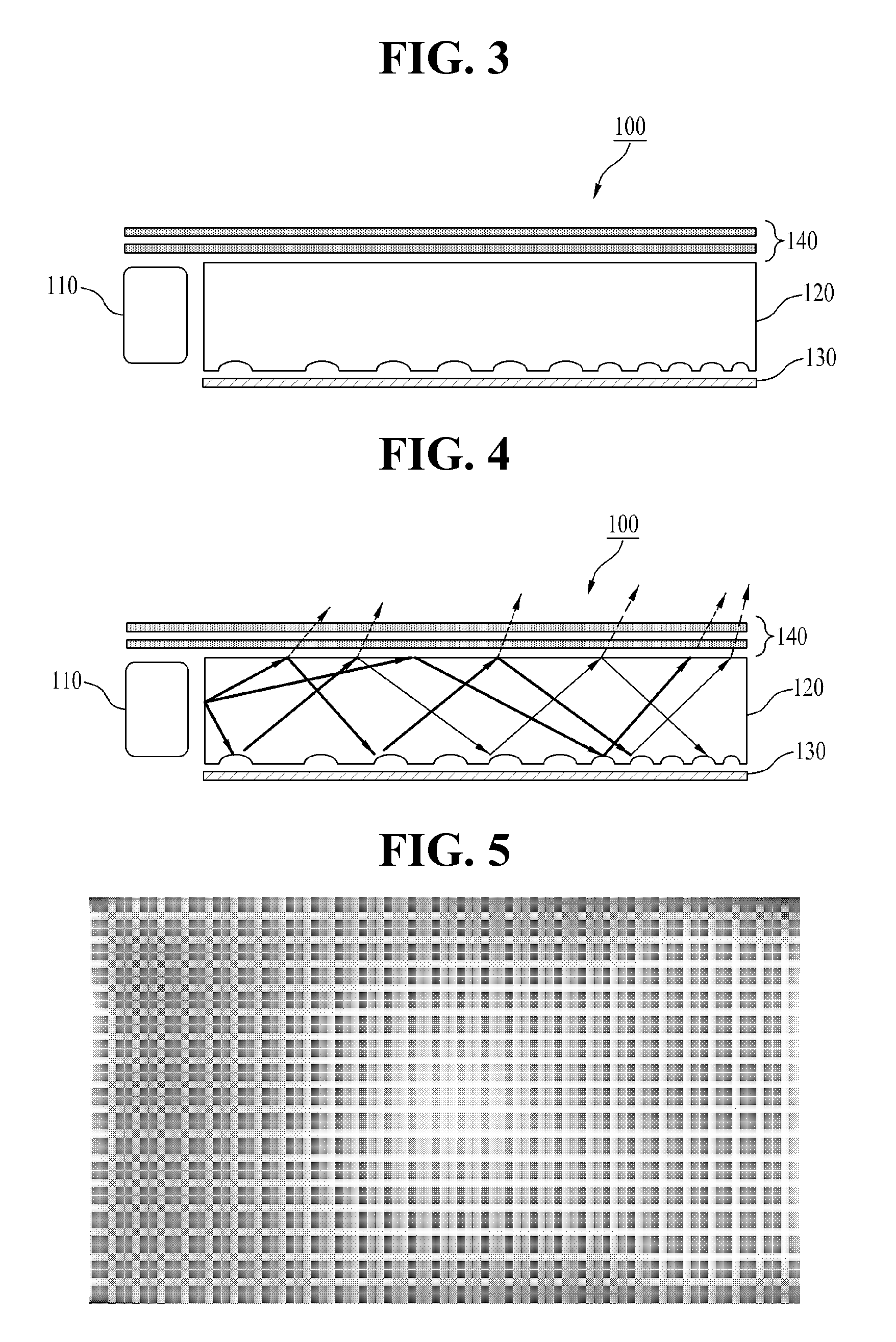
[0033]First, the backlight unit according to the embodiment of the present invention will be described with reference to FIGS. 3 to 5.

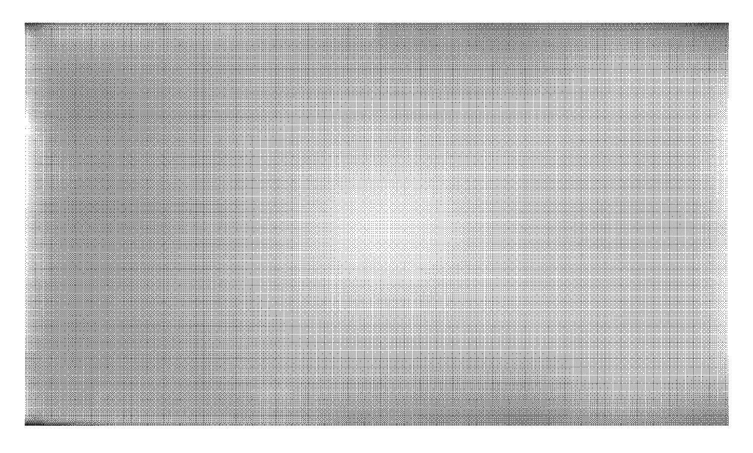
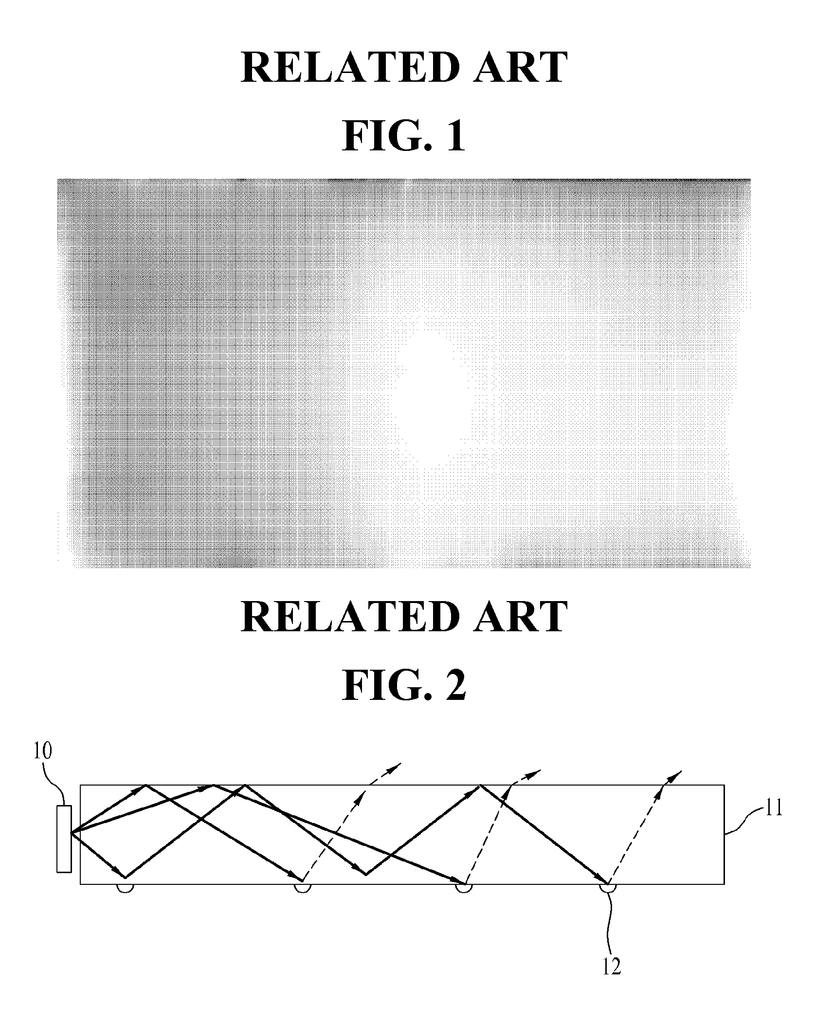
[0034]FIG. 3 is a sectional view of the backlight unit according to the embodiment of the present invention, FIG. 4 is a light emission diagram of the backlight unit illustrated in FIG. 3, and FIG. 5 is an image of emission light of a light guide plate of the backlight unit illustrated in FIG. 3.

[0035]As illustrated in FIG. 3, the backlight unit 100 according to the embodiment ...


PUM


Abstract

A light guide plate having a pattern to minimize generation of a dark zone and a backlight unit including the same are disclosed. The light guide plate includes an intaglio pattern consisting of recesses formed in a surface opposite to a light emitting surface thereof to have a cross section having major-axis and minor-axis diameters and depth, the recesses being spaced apart from one another in first and second directions by first and second distances respectively. The density of the intaglio pattern is directly proportional to the major-axis and minor-axis diameters and depth, and is inversely proportional to the first and second distances. The intaglio pattern has the minimum density in a first region adjacent to a light source, and the maximum density in a second region that is the maximum distance from the light source. A density ratio of the maximum density to the minimum density is 900.

Description

[0001]This application claims the benefit of Korean Patent Application No. P2010-0068961, filed on, Jul. 16, 2010, which is hereby incorporated by reference as if fully set forth herein.BACKGROUND OF THE INVENTION[0002]1. Field of the Invention[0003]The present invention relates to a light guide plate, which converts light, irradiated from a light source located at a corner thereof, into planar light, and a backlight unit including the same.[0004]2. Discussion of the Related Art[0005]Due to advancements in information technology, display devices for visually representing electric signals containing information have been developed rapidly. According to the development of display devices, a variety of flat display devices having excellent characteristics, such as a slim profile, light weight, and low electricity consumption have been developed and are replacing a conventional Cathode Ray Tube (CRT).[0006]Concrete examples of flat display devices include a Liquid Crystal Display (LCD) ...

Claims


Application Information

Patent Timeline
IPC IPC(8): F21V7/04
CPCG02B6/0036
Inventor LEE, DONG SEOKKIM, JAE JINBAE, JUN HOHWANG, YONG-IKLEE, HEE-KYUNG
Owner LG DISPLAY CO LTD
Why Eureka
Try Eureka