Frac nut and method of using

a technology of frac nut and nut, which is applied in the direction of threaded fasteners, pipe joints, fastening means, etc., to achieve the effect of saving considerable time and expense and being convenient to remov

Inactive Publication Date: 2012-01-19
R TECH
View PDF15 Cites 3 Cited by
  • Summary
  • Abstract
  • Description
  • Claims
  • Application Information

AI Technical Summary

Benefits of technology

[0009]A technical effect of the invention is the ability of the frac nut assembly to be more readily removable from a port fitting of a frac tank. As with conventional frac nuts, the frac nut assembly of this invention can be used to connect and disconnect a hose and its fitting to a frac tank with the use of a hammer or other large tool by tapping on the lugs of the assembly to cause the assembly to rotate. In the event that the assembly is difficult or impossible to remove from a frac tank, for example, the assembly is seized to a hose fitting as a result of corrosion, contamination by the liquid stored in a tank, or various other possible environmental conditions, the members of the assembly can be disassembled from each other. Such a capability is in contrast to a traditional one-piece frac nut, which if seized to a hose fitting is not removable from a frac tank as a result of the frac nut being captured on the frac tank fitting by the presence of the shoulder of the frac nut and the flange of the frac tank fitting. Consequently, removal of a seized frac nut traditionally requires shutting down the entire frac tank network (which often includes multiple tanks plumbed together through the frac assembly), emptying the tank if it contains a combustible fluid, possibly moving the tank to a safe location for repair, cutting off the tank port fitting, removing the frac nut from the fitting, installing a new frac nut on the fitting, welding the fitting to the frac tank, and then putting the frac tank back into service. As a result, it should be apparent that multiple-piece frac nuts of the present invention have the potential for saving considerable time and expense in the event that the frac nuts become seized.
[0010]Other aspects and advantages of this invention will be better appreciated from the following detailed description.

Problems solved by technology

In the event that the assembly is difficult or impossible to remove from a frac tank, for example, the assembly is seized to a hose fitting as a result of corrosion, contamination by the liquid stored in a tank, or various other possible environmental conditions, the members of the assembly can be disassembled from each other.

Method used


Image

  • Frac nut and method of using
  • Frac nut and method of using
  • Frac nut and method of using

Examples


Embodiment Construction

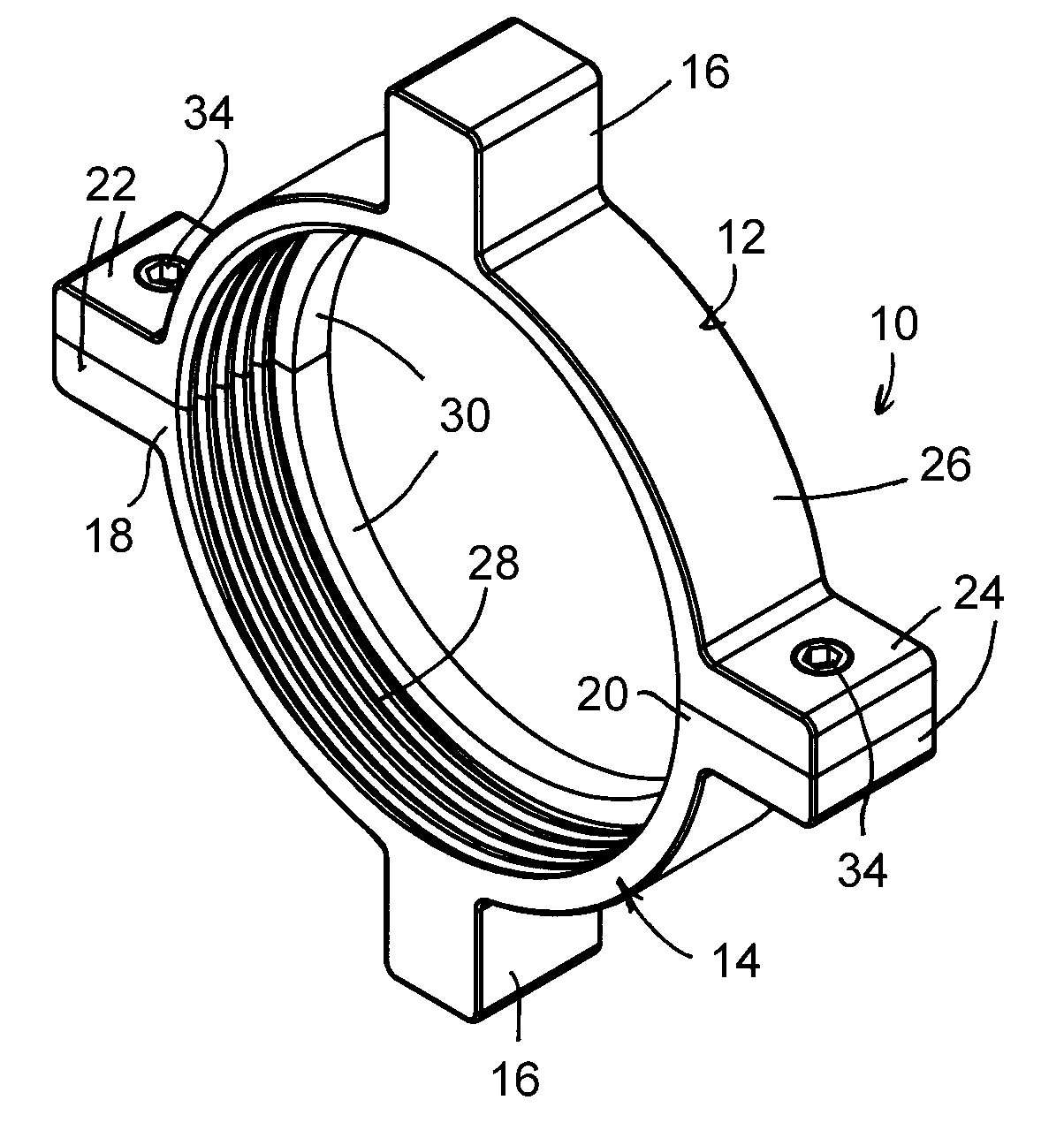
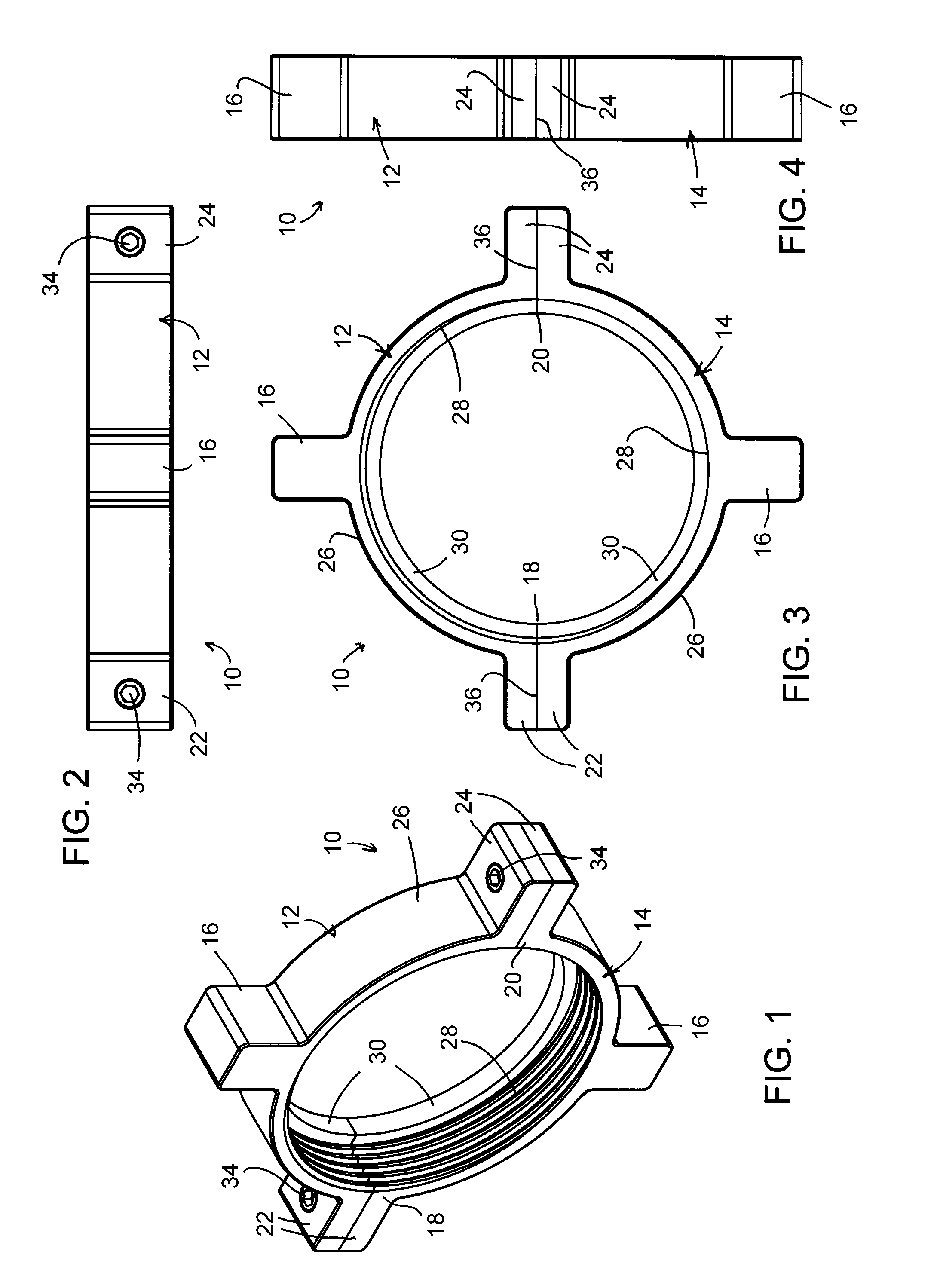
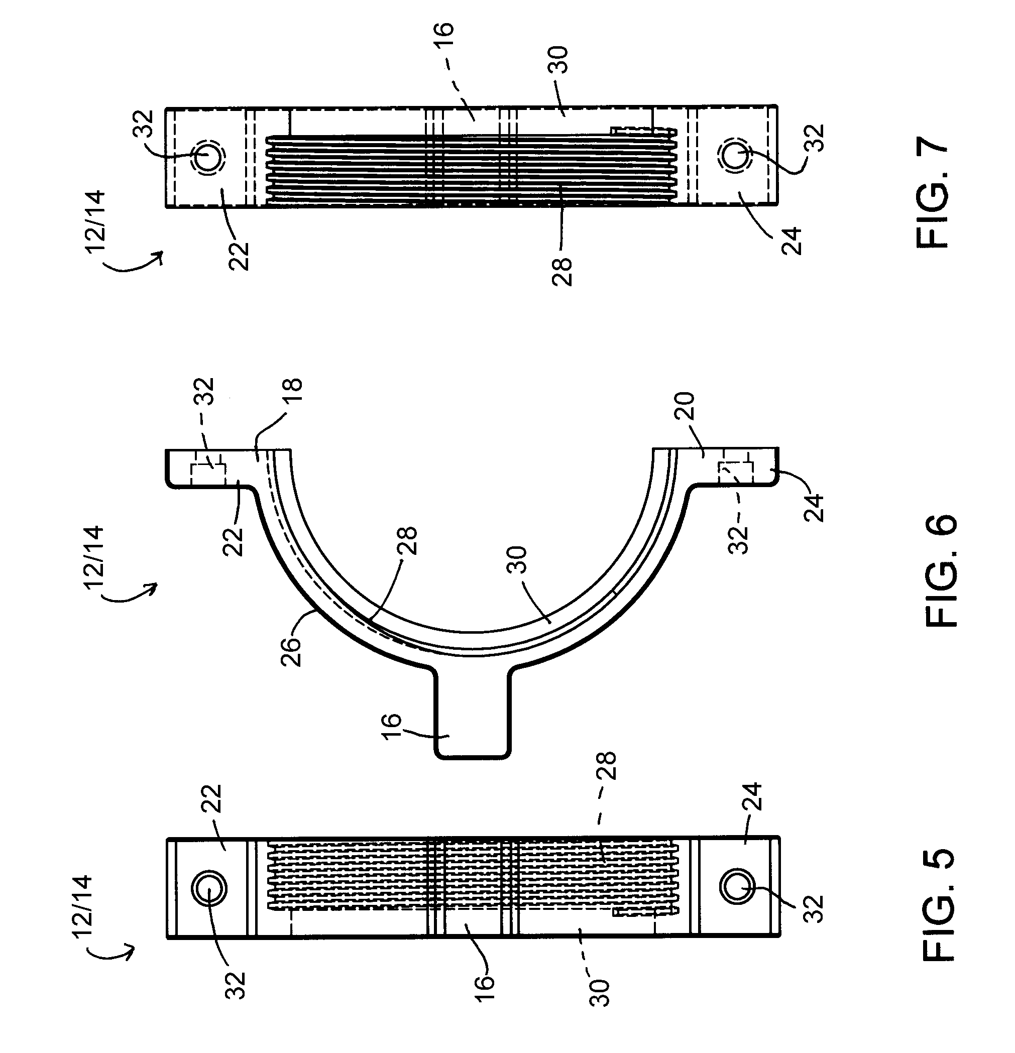
[0016]FIGS. 1 through 8 represent a frac nut assembly 10 according to an embodiment of the present invention. The assembly 10 has an annular shape comprised of two entirely separate members 12 and 14, represented as halves of the assembly 10, such that each member 12 and 14 has an arcuate shape that roughly defines a 180 degree arc. Each member 12 and 14 has a full-lug 16 located midway between the extremities 18 and 20 of its arc (i.e., at about 90 degrees), and half-lugs 22 and 24 located at the arc extremities 18 and 20, respectively. The full-lugs 16 and half-lugs 22 and 24 extend radially from the outer circumference 26 of the assembly 10, which is defined by the radially outward surfaces of the individual members 12 and 14 when assembled. The interior circumference of the assembly 10 has threads 28 for threadably engaging male threads (not shown) conventionally provided on a fitting of a hose or other suitable fluid conduit (not shown). As a result, the radially inward surface...


PUM


Abstract

A frac nut assembly and method of using the assembly. The assembly has an annular shape, an outer circumferential surface, an interior surface having female threads thereon at one axial end of the frac nut assembly and a shoulder that extends radially inward from an opposite axial end of the frac nut assembly, and at least two lugs radially protruding from the outer circumferential surface. The frac nut assembly further comprises at least two members that define the frac nut assembly when assembled together at planar radial interfaces.

Description

CROSS REFERENCE TO RELATED APPLICATIONS[0001]This application claims the benefit of U.S. Provisional Application No. 61 / 364,867, filed Jul. 16, 2010, the contents of which are incorporated herein by reference.BACKGROUND OF THE INVENTION[0002]The present invention generally relates to methods and devices for connecting tubing or pipelines, and more particularly for tubing or piping adapted to connect liquid storage tanks.[0003]Wide varieties of liquid storage tanks are employed in various industries. A frac tank is a particular example of a storage tank that was developed for the drilling and oil field industries and has found uses in various other fields where containment of a material is important for safety and environmental reasons. Frac tanks typically have liquid capacities in excess of 10,000 gallons (about 40,000 liters), and may be equipped with wheels to facilitate the transport of the tank between job sites. Their large capacities, mobility, and rugged designs make frac ta...

Claims


Application Information

Patent Timeline
Patent Type & Authority Applications(United States)
IPC IPC(8): F16B37/08
CPCF16B37/0892F16L19/0286F16L19/0231
Inventor RIES, JASON WAYNE
Owner R TECH
Why Eureka
Try Eureka