Near-wall serpentine cooled turbine airfoil

a turbine airfoil and serpentine technology, which is applied in the direction of engine fuction, machine/engine, engine manufacturing, etc., can solve the problems of film cooling being inefficient, moving along the inner surface of the airfoil, and interfering with the impingement j

Active Publication Date: 2012-01-19
MIKRO SYSYTEMS INC +1
View PDF7 Cites 21 Cited by
  • Summary
  • Abstract
  • Description
  • Claims
  • Application Information

AI Technical Summary

Problems solved by technology

Film cooling can be inefficient, because so many holes are needed that a high volume of cooling air is required.
A disadvantage is that warmer post-impingement air moves along the inner surfaces of the airfoil and interferes with the impingement jets.
Air in such channels is much cooler at the beginning of the flow sequence, so it can cool the airfoil unevenly.

Method used


Image

  • Near-wall serpentine cooled turbine airfoil
  • Near-wall serpentine cooled turbine airfoil
  • Near-wall serpentine cooled turbine airfoil

Examples


Embodiment Construction

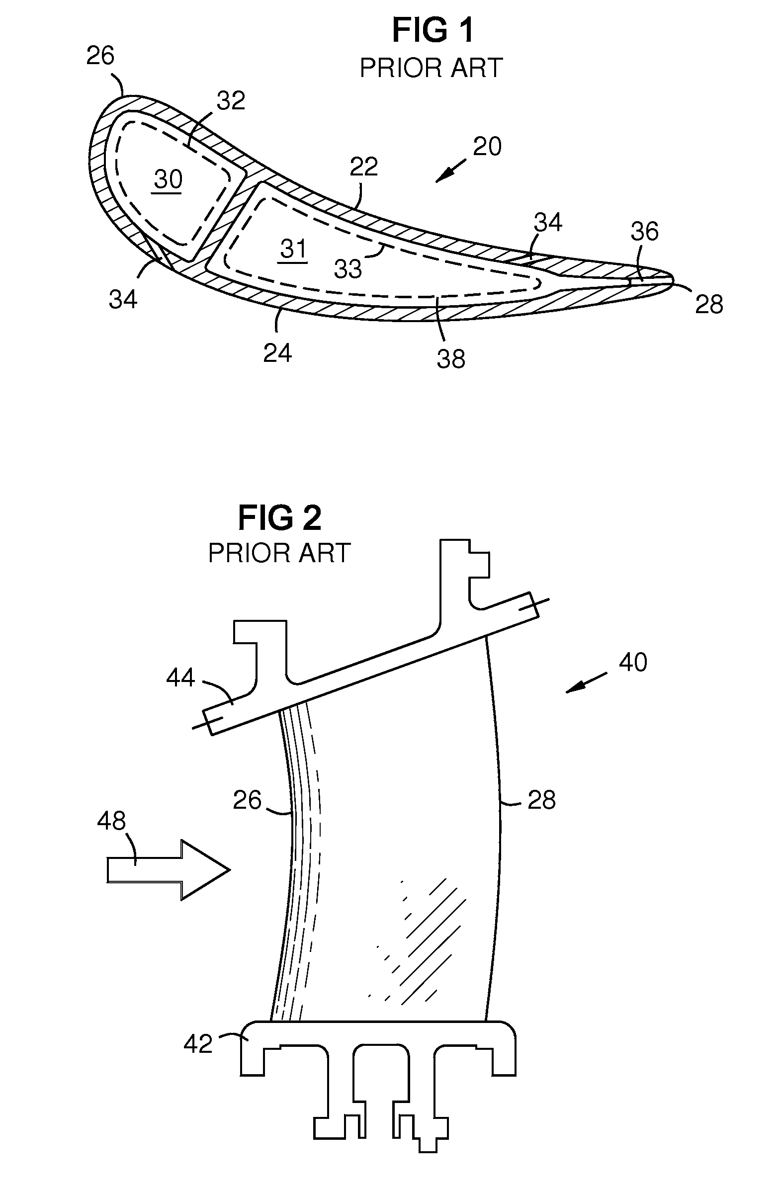
[0016]FIG. 1 is a transverse sectional view of a prior art turbine vane 20 with a pressure side wall 22, a suction side wall 24, a leading edge 26, a trailing edge 28, internal cooling channels 30, 31, impingement cooling baffles 32, 33, film cooling holes 34, and coolant exit holes 36. The impingement cooling baffles are thin-walled tubes inserted into the cooling channels 30, 31. They are spaced apart from the channel walls. Cooling air enters an end of each impingement baffle 32, 33, and flows span-wise within the vane. It exits impingement holes 38, and impinges on the walls 22, 24.

[0017]FIG. 2 shows a side view of a prior art curved turbine vane 40 that spans between radially inner and outer platforms 42, 44. The platforms are mounted in a circular array of adjacent platforms, forming inner and outer shrouds that define an annular flow path between them for a working gas 48 that passes over the vanes.

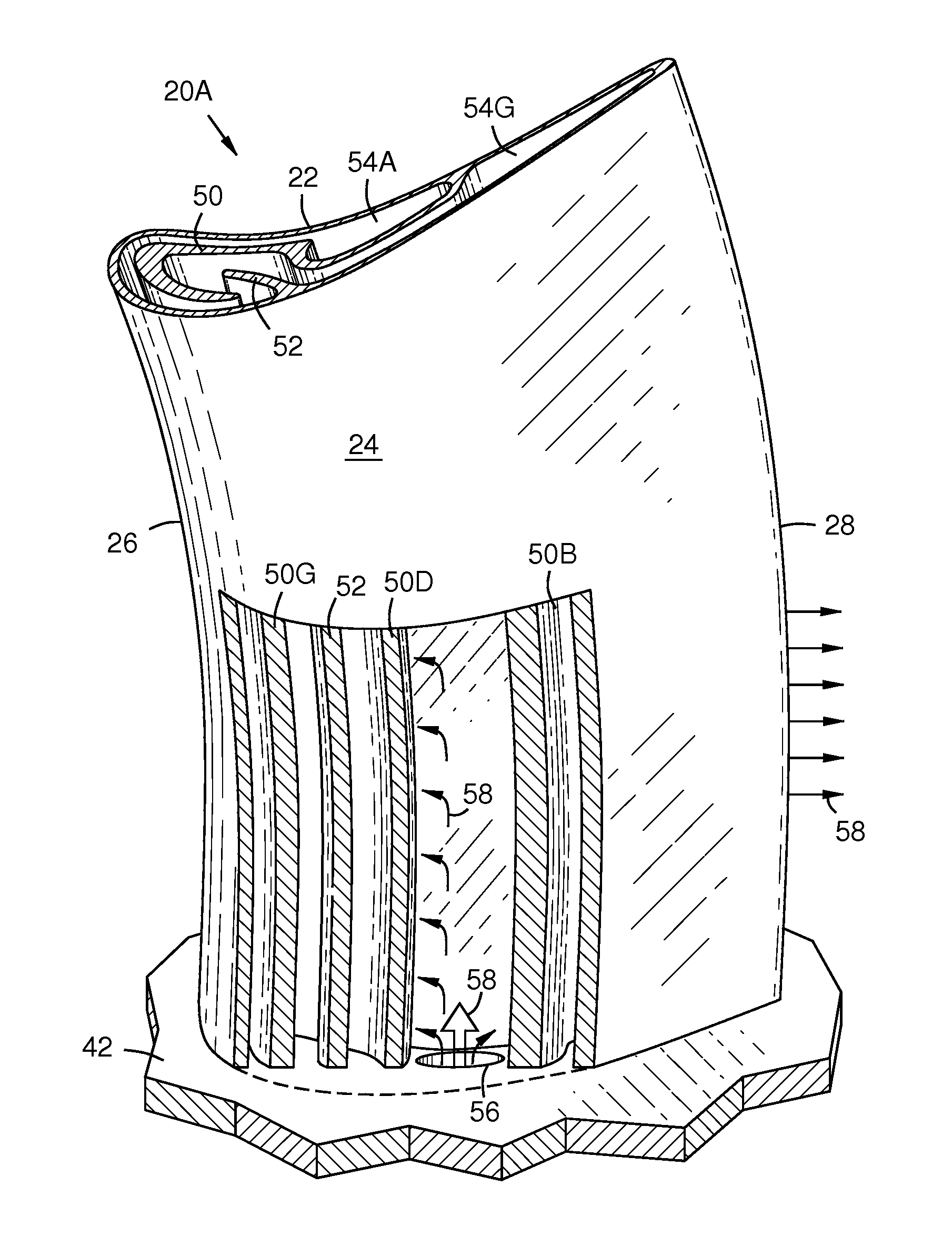
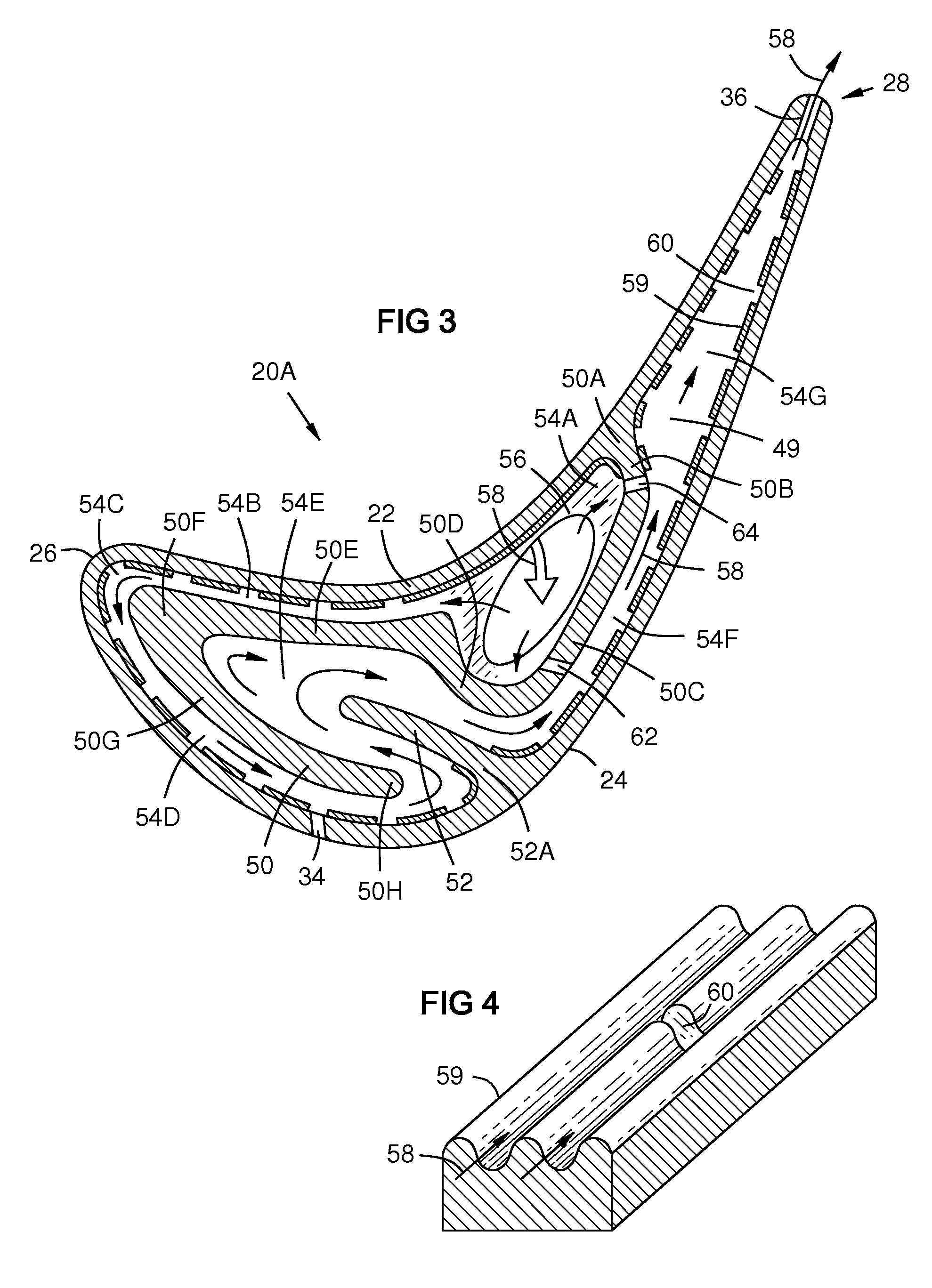
[0018]FIG. 3 shows a transverse section of an airfoil with a pressure side wal...


PUM


Abstract

A serpentine coolant flow path (54A-54G) formed by inner walls (50, 52) in a cavity (49) between pressure and suction side walls (22, 24) of a turbine airfoil (20A). A coolant flow (58) enters (56) an end of the airfoil, flows into a span-wise channel (54A), then flows forward (54B) over the inner surface of the pressure side wall, then turns behind the leading edge (26), and flows back along a forward part of the suction side wall, then follows a loop (54E) forward and back around an inner wall (52), then flows along an intermediate part of the suction side wall, then flows into an aft channel (54G) between the pressure and suction side walls, then exits the trailing edge (28). This provides cooling matched to the heating topography of the airfoil, minimizes differential thermal expansion, revives the coolant, and minimizes the flow volume needed.

Description

STATEMENT REGARDING FEDERALLY SPONSORED DEVELOPMENT[0001]Development for this invention was supported in part by Contract Number DE-FC26-05NT42644, awarded by the United States Department of Energy. Accordingly, the United States Government may have certain rights in this invention.FIELD OF THE INVENTION[0002]This invention relates to coolant flow channels in turbine airfoils, and particularly in curved vanes.BACKGROUND OF THE INVENTION[0003]Stationary guide vanes and rotating turbine blades in gas turbines often have internal cooling channels. Cooling effectiveness is important in order to minimize thermal stress on these airfoils. Cooling efficiency is important in order to minimize the volume of air diverted from the compressor for cooling.[0004]Film cooling provides a film of cooling air on outer surfaces of an airfoil via holes in the airfoil surface from internal cooling channels. Film cooling can be inefficient, because so many holes are needed that a high volume of cooling a...

Claims


Application Information

Patent Timeline
Patent Type & Authority Applications(United States)
IPC IPC(8): F01D5/18
CPCF01D5/187F05D2250/185F01D25/12F05D2260/22141F05D2260/202
Inventor LEE, CHING-PANG
Owner MIKRO SYSYTEMS INC
Why Eureka
Try Eureka