Power System Optimization and Verification for Embedded System Design

a technology of embedded systems and power systems, applied in the direction of electric digital data processing, liquid/fluent solid measurement, instruments, etc., can solve the problems of inability to exhaustively list specific examples, inability to determine what is and is not an embedded system, and inability to design functionalities into embedded systems that would not be feasible using hardware alon

Inactive Publication Date: 2012-01-19
PETIT EMMANUEL +2
View PDF5 Cites 7 Cited by
  • Summary
  • Abstract
  • Description
  • Claims
  • Application Information

AI Technical Summary

Problems solved by technology

In fact, embedded systems are so commonly in use today that it is not feasible to exhaustively list specific examples.
The term “embedded system” does not have a precise definition, and determining what is and is not an embedded system can be difficult.
Furthermore, functionalities can be designed into an embedded system that would not be feasible using hardware alone.
As the number of components within an embedded system increases and as the number of power states for each component increases, designing a comprehensive power management solution for the embedded system becomes exponentially more difficult.

Method used


Image

  • Power System Optimization and Verification for Embedded System Design
  • Power System Optimization and Verification for Embedded System Design
  • Power System Optimization and Verification for Embedded System Design

Examples


Embodiment Construction

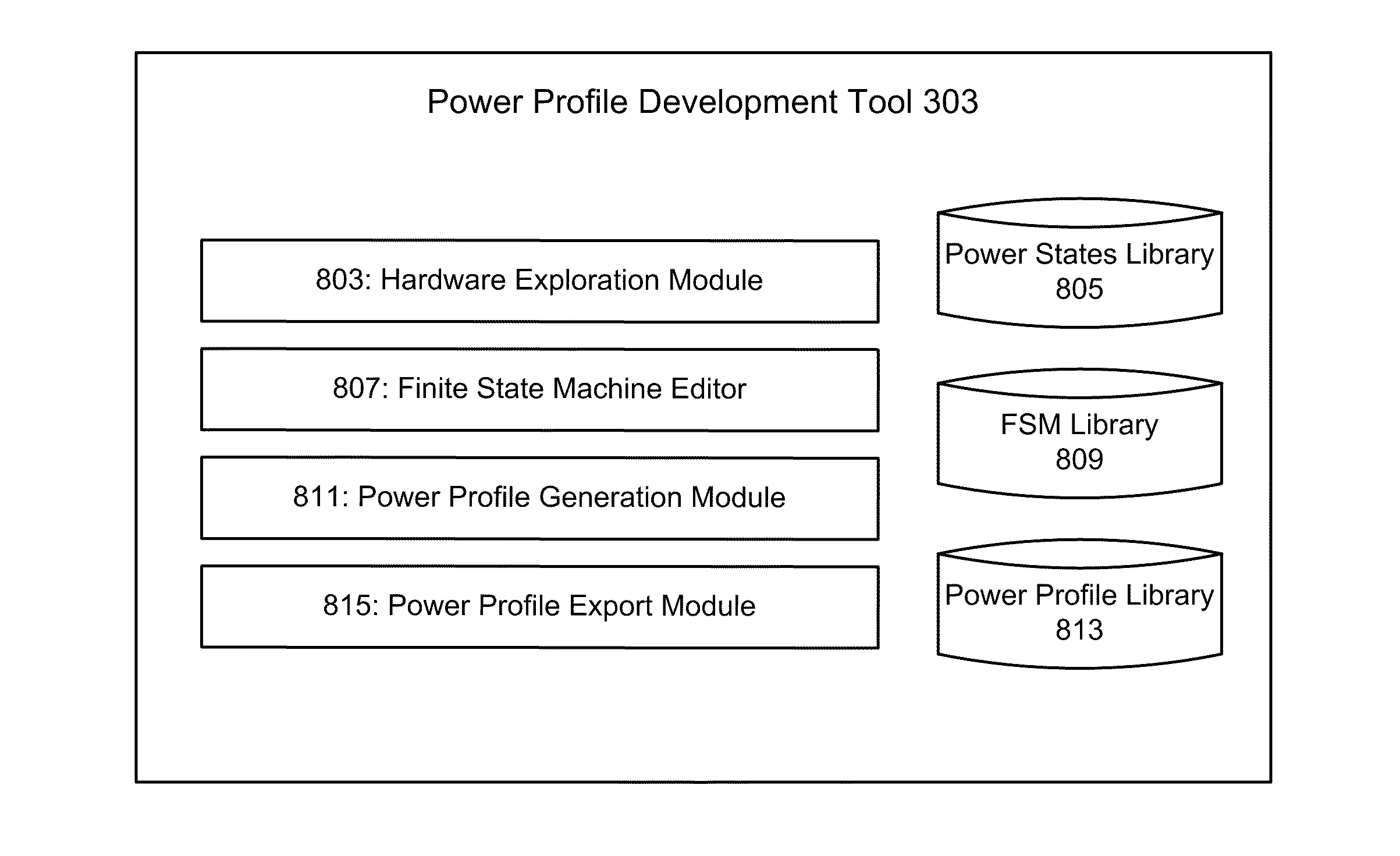
[0030]The operations of the disclosed implementations may be described herein in a particular sequential order. However, it should be understood that this manner of description encompasses rearrangements, unless a particular ordering is required by specific language set forth below. For example, operations described sequentially may in some cases be rearranged or performed concurrently. Moreover, for the sake of simplicity, the illustrated flow charts and block diagrams typically do not show the various ways in which particular methods can be used in conjunction with other methods.

[0031]It should also be noted that the detailed description sometimes uses terms like “generate” to describe the disclosed implementations. Such terms are often high-level abstractions of the actual operations that are performed. The actual operations that correspond to these terms will often vary depending on the particular implementation.

[0032]As stated above, various implementations of the invention pro...


PUM


Abstract

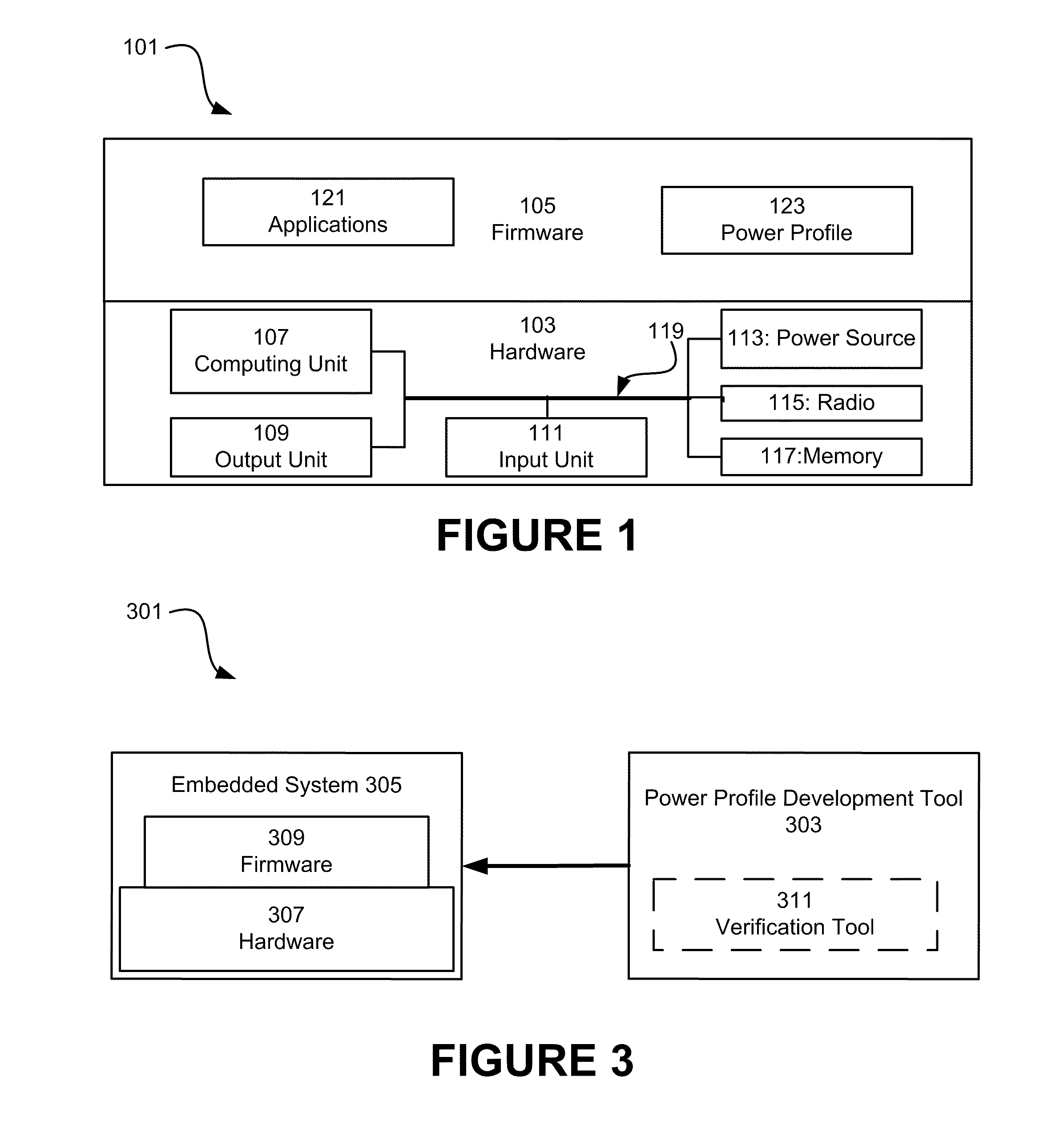
Tools and methods for developing and verifying a power management solution for an embedded system are provided. The firmware for an embedded system is partitioned into layers, including a control layer. The control layer implements a high-level power management behavior for the embedded system. A power profile development tool is also provided. The tool includes modules for describing the power functioning of the hardware of the embedded system, defining the desired power management behavior of the embedded system, and configuring the control layer within the firmware for the embedded system to implement the desired power management behavior. Furthermore, modules that interface with the embedded system and receive power system events and power status information and simulating the expected power management behavior based in part upon the received power event data and comparing the simulated behavior to the received power status behavior may also be provided.

Description

RELATED APPLICATIONS[0001]This application claims priority under 35 U.S.C. §119(e) to U.S. Provisional Patent Application No. 61 / 307,865 entitled “Optimization and Verification for Power System Design” filed on Feb. 25, 2010, and naming Emmanuel Petit et al. as inventors, which application is incorporated entirely herein by reference.FIELD OF THE INVENTION[0002]The invention relates to the design of embedded electronic systems. More specifically, various implementations of the invention are applicable to optimizing and verifying the power requirements of an embedded system.BACKGROUND OF THE INVENTION[0003]In general, an embedded system may be described as a special purpose computing system designed to perform one or a few dedicated functions. Embedded systems are commonly used in consumer devices like personal digital assistants, mobile phones, videogame consoles, microwaves, washing machines, alarm systems, and digital cameras. In addition to the consumer space, embedded systems ar...

Claims


Application Information

Patent Timeline
Patent Type & Authority Applications(United States)
IPC IPC(8): G06F1/26
CPCG06F1/3203G06F2217/78G06F17/5045G06F30/30G06F2119/06
Inventor PETIT, EMMANUELSHALAN, MOHAMEDAHMAD, IRFAN
Owner PETIT EMMANUEL
Why Eureka
Try Eureka