CPP-type thin film magnetic head provided with side shields

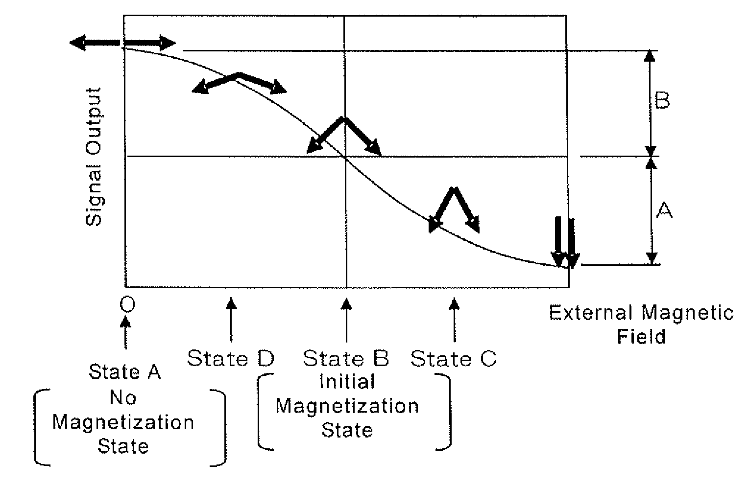
a thin film magnetic head and side shield technology, applied in the field of thin film magnetic head, can solve the problems of narrow effective track width and further increase the dispersion of output, and achieve the effect of improving the linearity between the external magnetic field and the output of signal signals, and increasing the track density of the head

Active Publication Date: 2011-03-03
TDK CORPARATION
View PDF4 Cites 117 Cited by
  • Summary
  • Abstract
  • Description
  • Claims
  • Application Information

AI Technical Summary

Benefits of technology

[0008]The present invention relates to a thin film magnetic head disposed with a magnetoresistive (MR) stack having a first MR magnetic layer, a second MR magnetic layer, and a nonmagnetic intermediate layer. Magnetization directions of the first and second MR magnetic layers change according to an external magnetic field. The nonmagnetic intermediate layer is disposed between the first MR magnetic layer and the second MR magnetic layer and contacts the both layers. The object of the present invention is to provide the thin film magnetic head with such a configuration. A track density of the head easily increases, and linearity between the external magnetic field and a signal output is improved.
[0010]In the thin film magnetic head having the above-mentioned configuration, the first and second MR magnetic layers are magnetized in antiparallel directions to each other by the magnetic fields generated from the first magnetic control layer of the first shield layer and the second magnetic control layer of the second shield layer where there is no additional magnetic field. Since the first and second MR magnetic layers actually receive the bias magnetic field, being in the orthogonal direction to the ABS and generated from the bias magnetic field application layer, the first and second MR magnetic layers are magnetized into an intermediate state defined as a half-parallel state and a half-antiparallel state. The middle state is defined as an initial magnetization state. When the recording medium applies the external magnetic field under the initial magnetization state, a relative angle formed by the magnetization directions of the first and second MR magnetic layers changes according to a size (or amount) and a direction of the external magnetic field. Therefore, it becomes possible to detect the external magnetic field using a magnetoresistive effect.
[0011]An influence of a magnetic field from an adjacent track is suppressed by a pair of the side shield layers disposed in the both sides of the MR stack in the track width direction. Therefore, the track density easily increases. Because each of a pair of side shield layers has a pair of magnetic layers that are antiferromagnetically exchange-coupled through a Ru layer (or side shield Ru layer), each of the side shield layers has little spontaneous magnetization as a whole. As mentioned above, each of the side shield layers generally has a long and narrow shape in the track width direction, and is easily magnetized in the track width by the shape anisotropy effect if each of the side shields has spontaneous magnetization. However, according to the present invention, even if spontaneous magnetization is generated in one side of the magnetic layers that configure each of the side shields, the generated magnetization is canceled because of the magnetization generated in the other side of the magnetic layer by the exchange-coupling. Therefore, the side shield layers are minimally magnetized as a whole. As a result, the first and second MR magnetic layers easily receive only the bias magnetic field in the orthogonal direction to the ABS. Therefore, it becomes possible to provide a thin film magnetic head that has increased arrangement density in the circumferential direction of the track and improved linearity between the external magnetic field and the signal output.

Problems solved by technology

Even if an element size is the same, the side shield layers may narrow an effective track width.
This phenomenon deteriorates linearity between the external magnetic field and a signal output at the time of the external magnetic field being applied, and further increases a dispersion of the output.

Method used


Image

  • CPP-type thin film magnetic head provided with side shields
  • CPP-type thin film magnetic head provided with side shields
  • CPP-type thin film magnetic head provided with side shields

Examples


Embodiment Construction

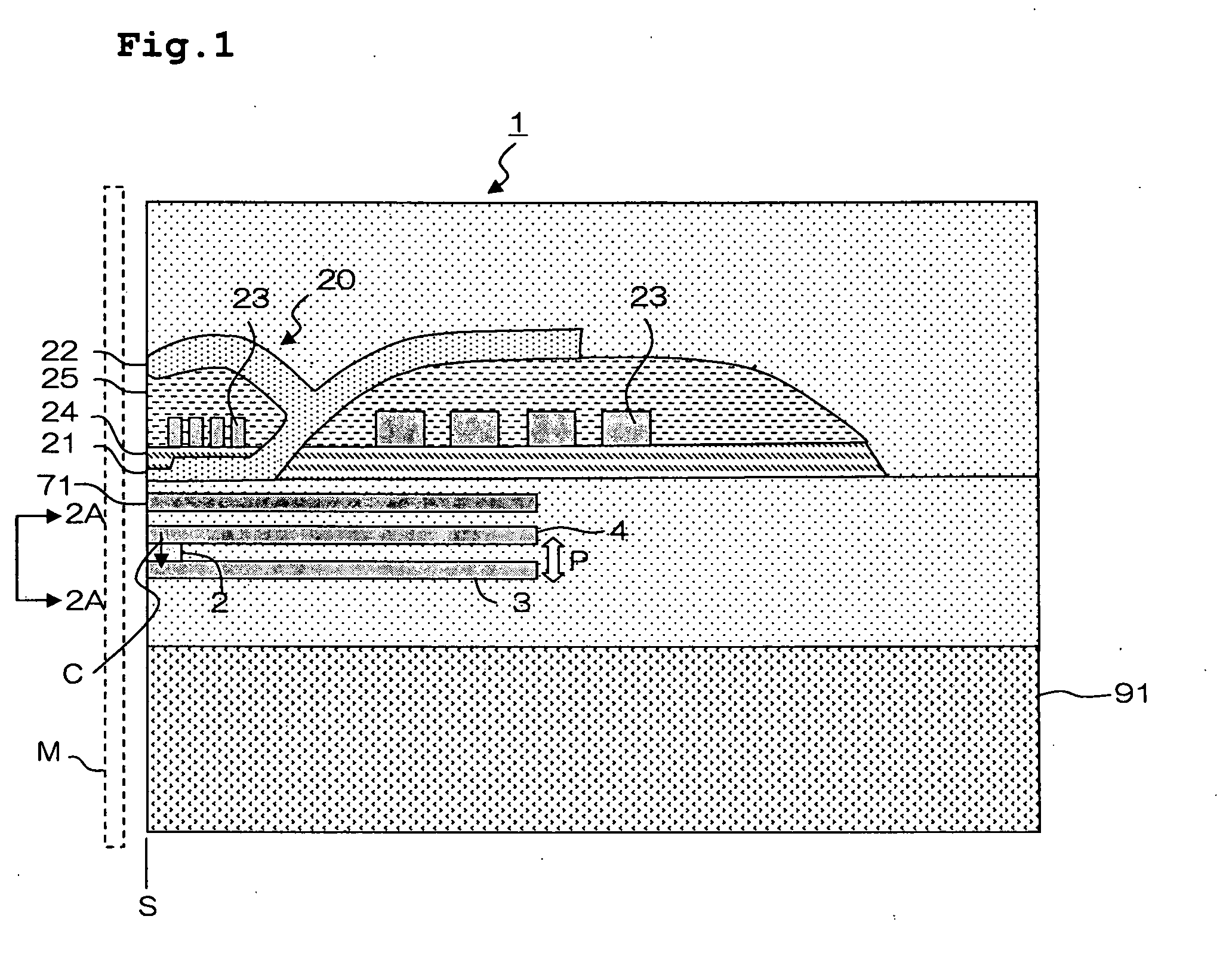
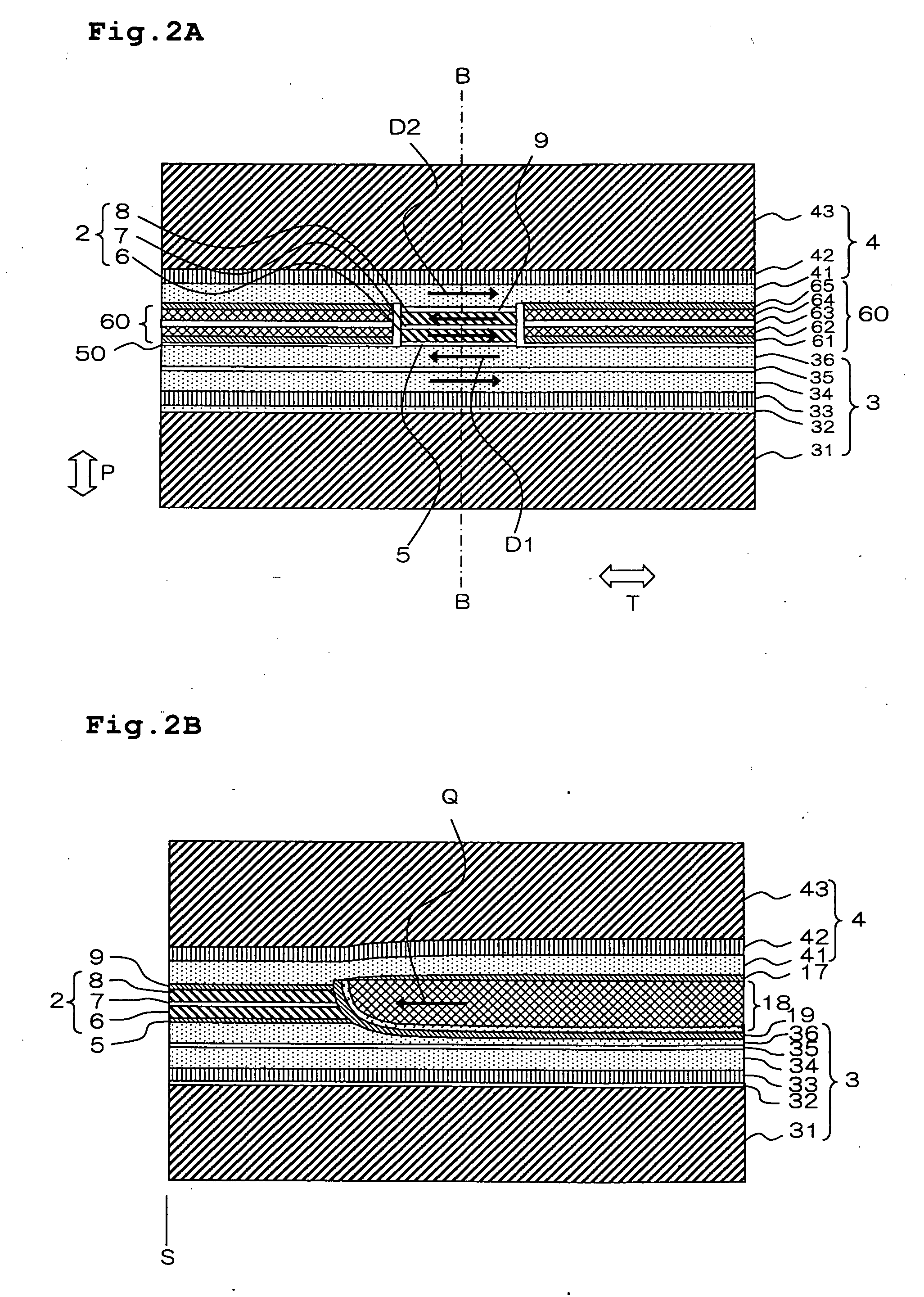
[0027]Hereafter, a thin film magnetic head according to one embodiment of the present invention will be explained with reference to the drawings. FIG. 1 is a side sectional view of the thin film magnetic head according to the present invention. FIG. 2A is a side view of the reproducing element part of the thin film magnetic head seen from the 2A-2A direction, i.e., from an air bearing surface (ABS) S, in FIG. 1. FIG. 2B is a sectional view of the reproducing element part of the thin film magnetic head seen from the same direction as FIG. 1 is shown. The ABS S is a surface of a thin film magnetic head 1 on a side facing a recording medium M.

[0028]The thin film magnetic head 1 includes a magnetoresistive (MR) stack 2 and first and second shield layers 3 and 4 that sandwich the MR stack 2 in a film surface orthogonal direction P of the MR stack 2. The thin film magnetic head 1 is a current perpendicular to plane (CPP) type in which a sense current flows in the film surface orthogonal d...


PUM

PropertyMeasurementUnit
thicknessaaaaaaaaaa
widthaaaaaaaaaa
thicknessaaaaaaaaaa

Abstract

A thin film magnetic head includes first and second shield layers that are positioned on both sides of a magnetoresistive (MR) stack with respect to a film surface orthogonal direction; a first exchange-coupling layer that is positioned between the MR stack and the first shield layer and that generates an exchange-coupling between a first magnetoresistive (MR) magnetic layer and a first magnetic control layer of the first shield layer; a second exchange-coupling layer that is positioned between the MR stack and the second shield layer and that generates an exchange-coupling between a second magnetoresistive (MR) magnetic layer and a second magnetic control layer of the second shield layer; a bias magnetic field application layer that is disposed at an opposite surface of the MR stack from an air bearing surface (ABS) and that applies a bias magnetic field to the MR stack in a direction orthogonal to the ABS; and pair of side shield layers that are positioned at both sides of the MR stack with respect to a track width direction. Each of the side shield layers includes a pair of magnetic layers that are antiferromagnetically exchange-coupled through a side shield ruthenium layer.

Description

BACKGROUND OF THE INVENTION[0001]1. Field of the Invention[0002]The present invention relates to a thin film magnetic head. Specifically, it relates to the composition of a side shield (or side shield layer) of the thin film magnetic head provided with a pair of magnetic layers whose magnetization directions change according to an external magnetic field.[0003]2. Description of the Related Art[0004]Conventionally, a spin valve head is known as a head having high power and high sensitivity, used for a hard disk drive (HDD). In order to fix a magnetization direction of one ferromagnetic layer of a pair of ferromagnetic layers that are disposed on both sides of a nonmagnetic intermediate layer, an antiferromagnetic layer made of a material such as IrMn is used for the spin valve head. Since the antiferromagnetic layer has a relatively thicker film thickness, and may cause a restriction of further high recording density (narrowing a read gap), a new concept attempts to narrow a read gap...

Claims


Application Information

Patent Timeline
Patent Type & Authority Applications(United States)
IPC IPC(8): G11B21/16G11B5/33G11B5/48
CPCB82Y10/00B82Y25/00G11B5/3951G11B2005/3996G11B5/3932G11B5/3912
Inventor MIYAUCHI, DAISUKEKAWAMORI, KEITAMACHITA, TAKAHIKO
Owner TDK CORPARATION
Why Eureka
Try Eureka