
Safety curtain structure

a curtain structure and safety technology, applied in the direction of door/window protective devices, buckles, mechanical devices, etc., can solve the problems of not meeting the requirement of loop pulling strings, and not meeting the requirement of adjusting the height of a large curtain

Inactive Publication Date: 2012-01-26
HUANG HSIEN TE
View PDF4 Cites 24 Cited by
  • Summary
  • Abstract
  • Description
  • Claims
  • Application Information

AI Technical Summary

Benefits of technology

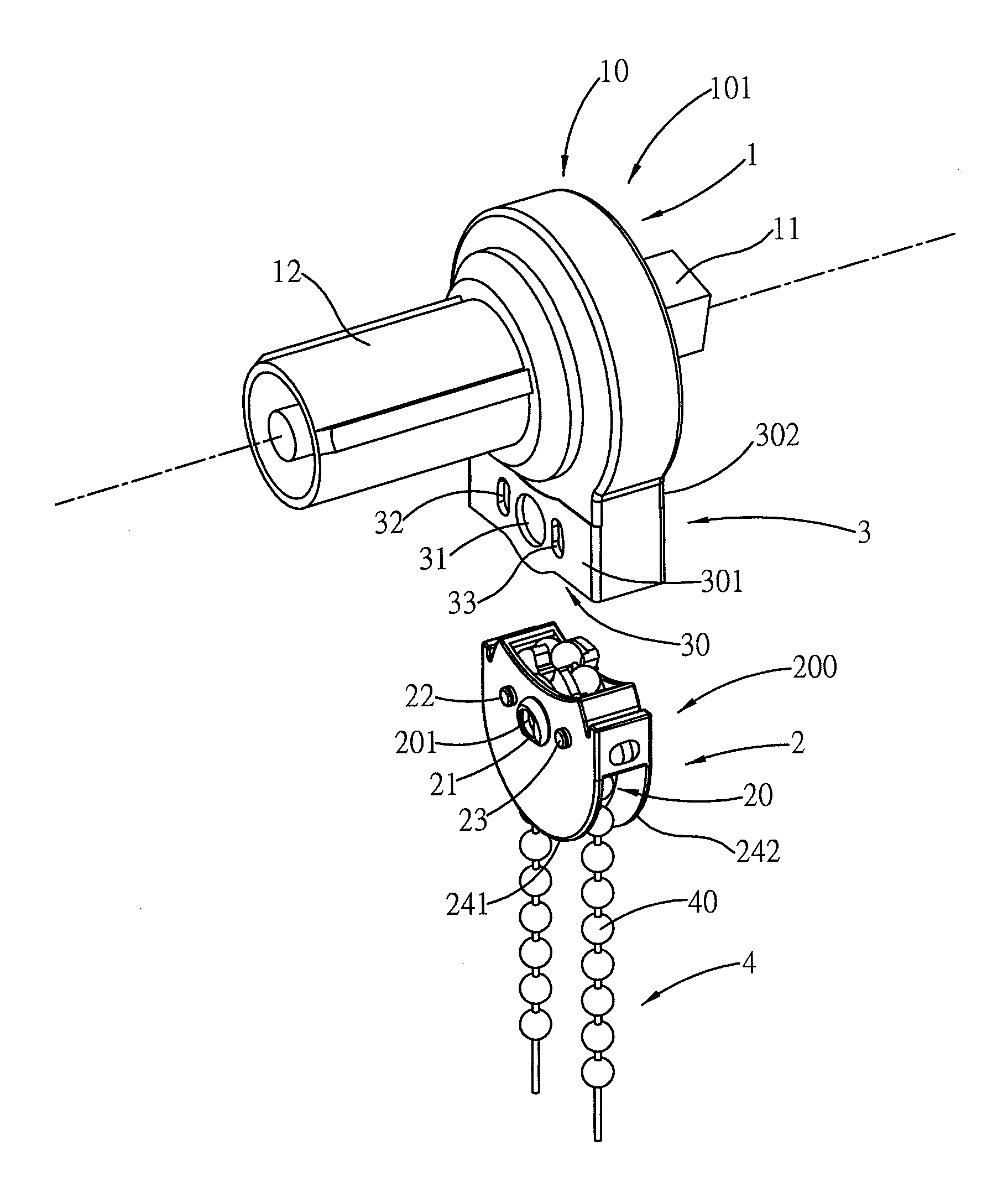
[0008]Therefore, it is a primary objective of the invention to provide a safety curtain structure, such that if a pulling string of a curtain is wound around a child's limb by accident, the pulling string will be separated from a brake mechanism immediately to release the binding force of the pulling string, so as to achieve the desired safety effect, and in normal operation, the angle of latching the snap-in frame can be changed to achieve a secured connection, such that the pulling string can transmit a braking force for a reasonable load to meet the requirement of adjusting the light shading area of the curtain.
[0009]A second objective of the present invention is to provide a method that forms a pivot hole and two symmetrical conjugated first and second kidney-shaped holes on the cartridge and designs a pivot ring with an evacuated movable plane to the snap-in frame, such that after the two symmetrical first and second stop pegs are combined, and a child's limb is wound by the pulling string accidentally, pulldown forces are produced on both sides of the pulling string simultaneously and indirectly acted onto one of the stop pegs to form a fulcrum, and the distance between the fulcrum and a circular tangent position on another side of the moving / braking wheel is the length of the lever that can produce a much better lever effect and increase the squeezing force, so that the pivot ring can overcome the coupling force of the cartridge to expand the internal span and drive the snap-in frame of the pulling string to be separated from the cartridge easily, so as to achieve the quick-release safety effect.
[0010]A third objective of the present invention is to pivotally connect the moving / braking wheel into the pivot hole of the snap-in frame through a wheel axle, such that after the moving / braking wheel is braked by a chain, indirect moving frictional forces of the moving / braking wheel and the snap-in frame synchronously rotate the snap-in frame at an initial time, such that the pivot ring and the first and second stop pegs of the snap-in frame can produce a change of angular position to obtain at least one latch point, and the latch point is provided for maintaining the connection of the snap-in frame and the cartridge to allow users to apply a force fully and freely at a side of the chain.
[0011]A four objective of the present invention is to provide a snap-in frame formed by two opposite flat plates and a connecting plate connected laterally and separately to the flat plates, and the interior of the snap-in frame is provided for pivotally installing a moving / braking wheel, and a through opening is formed between an external surface of the moving / braking wheel and the connecting plate and provided for passing a chain and providing a blocking effect, such that a movable connection between the snap-in frame and the chain can be achieved normally, and such arrangement can prevent small snap-in frame from falling out, missing, or eaten by children accidently after the snap-in frame is separated from the cartridge.

Problems solved by technology

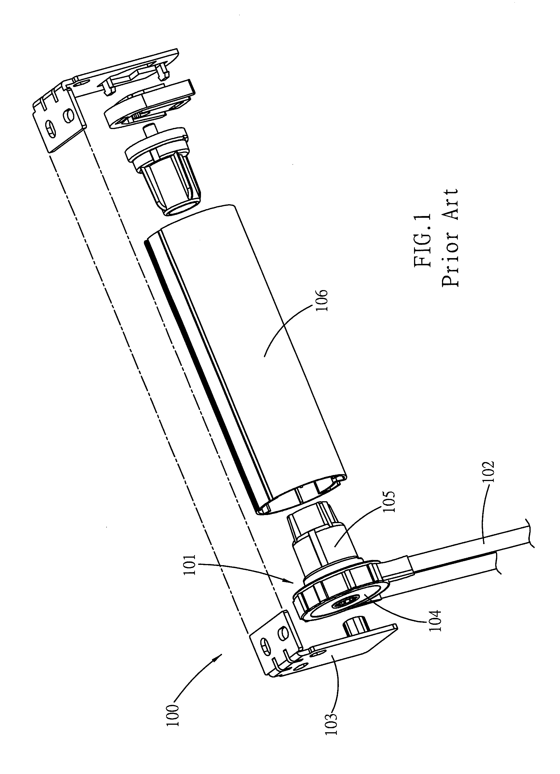
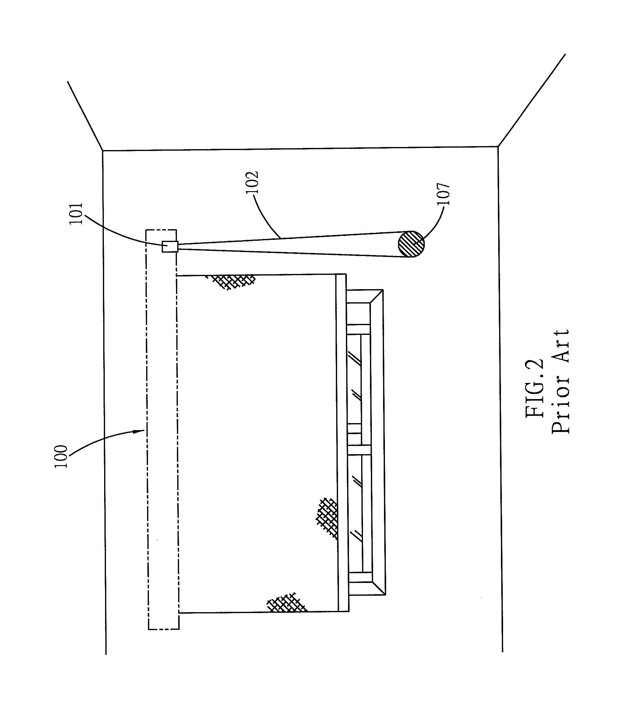
In addition, many designs and methods related to the safety protection of a puling string can be found in IPC A47H-003 / 04, but none of them can meet the requirement for the loop-shaped pulling string.
In the design of the aforementioned patents M253301 and M245951, the loop-shaped pulling string is connected to other components with a detachable break, which will restrict the loop movement of the pulling string to one round only, and cannot satisfy the requirement of adjusting the height of a large curtain.

Method used


Image

  • Safety curtain structure
  • Safety curtain structure
  • Safety curtain structure

Examples


Embodiment Construction

[0030]The technical characteristics and effects of the present invention will be apparent with the detailed description of preferred embodiment together with the illustration of related drawings as follows.

[0031]The present invention provides a safety curtain structure having a loop-shaped pulling string, such that when the curtain is operated in a normal condition, a force can be applied fully to the pulling string (or chain) for the operation, and the pulling string can be separated from a brake mechanism quickly during an emergency situation, so as to release the binding force of the pulling string and achieve the safety effect, wherein a fulcrum is used for increase the moment to reduce the force required for the separation, so as to detach the pulling string from the brake mechanism easily.

[0032]With reference to FIG. 3 for a moving / braking unit 200 of the present invention, the moving / braking unit 200 is comprised of a snap-in frame 2 and a chain 4 flexibly connected to the sn...


PUM


Abstract

In a safety curtain structure, an assembly of a pulling string and a curtain brake mechanism can be separated easily when a force is applied onto the curtain pulling string by accident, such that a binding force of the pulling string can be released quickly to assure the safety for protecting children's limbs at a certain height, and allowing the pulling string to fully apply a force to a brake mechanism to satisfy the requirement of moving or stopping a reasonable load when a curtain is rolled normally.

Description

BACKGROUND OF THE INVENTION[0001]a) Field of the Invention[0002]The present invention relates to a safety curtain structure of operating the system, and more particularly to a safety curtain structure for immediately separating a pulling string from a curtain brake mechanism when a force is applied to the pulling string of the curtain by accident, such that the pulling string can be released quickly to achieve the safety effect of preventing a child's limbs from being wound by the pulling string accidentally, and a force can be applied fully to the pulling string and transmitted to a brake mechanism to provide the required force for rolling the curtain under a normal operation, and the main body of the present invention is a universal coupling brake mechanism, comprising a hub with an internal span formed at the bottom of the hub for expanding and contracting a cartridge and provided for embedding and combining a moving / braking unit, and a universal driving shaft capable of driving ...

Claims


Application Information

Patent Timeline
Patent Type & Authority Applications(United States)
IPC IPC(8): F16G11/10
CPCE06B9/326Y10T24/3982E06B2009/3265E06B9/42
Inventor HUANG, HSIEN-TE
Owner HUANG HSIEN TE
Learn More