Mechanical lockings of floor panels and a tongue blank

Active Publication Date: 2012-01-26
VÄLINGE INNOVATION AB
View PDF1 Cites 150 Cited by
  • Summary
  • Abstract
  • Description
  • Claims
  • Application Information

AI Technical Summary

Benefits of technology

[0011]The general objective of the present invention is to improve the function and strength of a side push locking system and particularly of those parts that ca

Problems solved by technology

The main disadvantage is that the tool will form a cavity 41 with a considerable depth as shown in FIG. 2d.
A side push locking system according to known technology that requires that a displacement groove is formed which is not parallel to the edge is very difficult to produce and deep grooves will have a negative effect on the stability and strength of the panel edge.
Such tongues

Method used


Image

  • Mechanical lockings of floor panels and a tongue blank
  • Mechanical lockings of floor panels and a tongue blank
  • Mechanical lockings of floor panels and a tongue blank

Examples


Embodiment Construction

[0051]FIG. 3a-3e shows a production method to form cavities 41a-d according to a cutter principle. Several cutters 70a-d could be used, one for each cavity. The forming could take place before or after forming of the profile. FIG. 3a shows that the cuter principle could form a cavity, which is smaller than the diameter of the cutter. FIG. 3e shows a cavity, which is larger than the diameter, if the panel and the tool are displaced in relation to each other. FIG. 3f shows a cavity, which is formed, as a blind hole comprising a solid upper part and an opening.

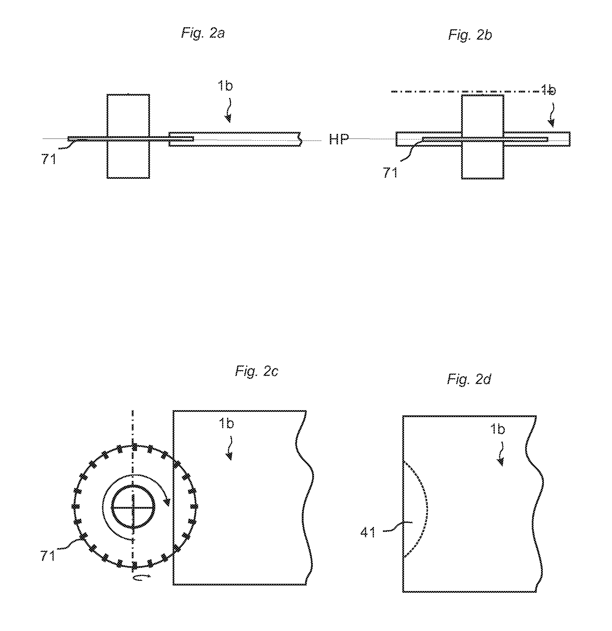
[0052]FIG. 4a-d show that the above mentioned forming could also be made with a saw blade principle where preferably several saw blades 71a-d preferably on the same axes, forms cavities 41a-d. The cavities are in this embodiment smaller than the diameter of the saw blades. They could of course be equal or larger.

[0053]FIG. 5a-d show a method to form the above mentioned cavities 41a-f with a screw cutter principle. Such forming co...


PUM


Abstract

Floor panels (1, 1′) are shown, which are provided with a mechanical locking system comprising tongue and grooves provided with protrusions and cavities which are displaceable in relation to each other.

Description

AREA OF INVENTION[0001]The invention generally relates to the field of floor panels with mechanical locking systems comprising a separate displaceable tongue allowing easy installation. The invention provides new improved locking systems and methods to install and disconnect building panels, especially floor panels and methods to produce the locking system.BACKGROUND OF THE INVENTION[0002]In particular, yet not restrictive manner, the invention concerns a mechanical locking system for rectangular floor panels with long and short edges, which could be installed with vertical folding. It should be emphasized that long and short edges are only used to simplify the description. The panels could also be square, they could have more than 4 edges and the adjacent edges could have angles other than 90 degrees. However, the invention is as well applicable to building panels in general. More particularly the invention relates mainly to the type of mechanically locking systems, which allow tha...

Claims


Application Information

Patent Timeline
IPC IPC(8): E04B5/00
CPCE04F15/02E04F2201/0138E04F2201/0153E04F2201/0169E04F15/02038E04F2201/0541E04F2201/0547E04F2201/0115E04F2201/0523
Inventor PERVAN, DARKOBOO, CHRISTIAN
Owner VÄLINGE INNOVATION AB
Why Eureka
Try Eureka