Coil Tubing Cable Head with Tool Release, Fluid Circulation and Cable Protection Features

a technology of cable head and tool release, which is applied in the direction of drilling casing, drilling pipes, and accessories for wells, etc., can solve the problems of limiting the flow rate at which the operator can pump fluid through the tubing for purposes, and being susceptible to damage, wear or failure,

Active Publication Date: 2012-01-26
SPENCE DEAN
View PDF2 Cites 22 Cited by
  • Summary
  • Abstract
  • Description
  • Claims
  • Application Information

AI Technical Summary

Benefits of technology

[0012]a locking mechanism disposed between said upper and lower housings for preventing said relative movement and thereby preventing shearing of said shearable connection when said locking mechanism is in a locked condition and allowing shearing of said shearable connection by said relative movement when said locking mechanism is in an unlocked condition;

Problems solved by technology

U.S. Pat. No. 6,196,325, which is herein incorporated by reference, suggests problems with use of only such a shear pin connection in a separable cable head structure, in that inadvertent shearing and resulting disconnect may occur during perforating operations and that the tensile strength of the tubing needs careful consideration in selecting suitable shear pins to prevent inadvertent failure of the tubing string during pulling thereof in an attempted disconnection from the tool.
While this closing of the fluid's flow path to cease circulation informs the operator of displacement of the piston, it also limits the flow rates at which the operator can pump down fluids through the tubing for purposes other than triggering the cable head's tool-release function.
Also, the conductor of the electric line exits the cable armor near the top of the cable head, leaving it exposed through most of the line's passage through the cable and thus potentially susceptible to damage, wear or failure by exposure to fluid passing through the cable head.

Method used


Image

  • Coil Tubing Cable Head with Tool Release, Fluid Circulation and Cable Protection Features
  • Coil Tubing Cable Head with Tool Release, Fluid Circulation and Cable Protection Features
  • Coil Tubing Cable Head with Tool Release, Fluid Circulation and Cable Protection Features

Examples


Embodiment Construction

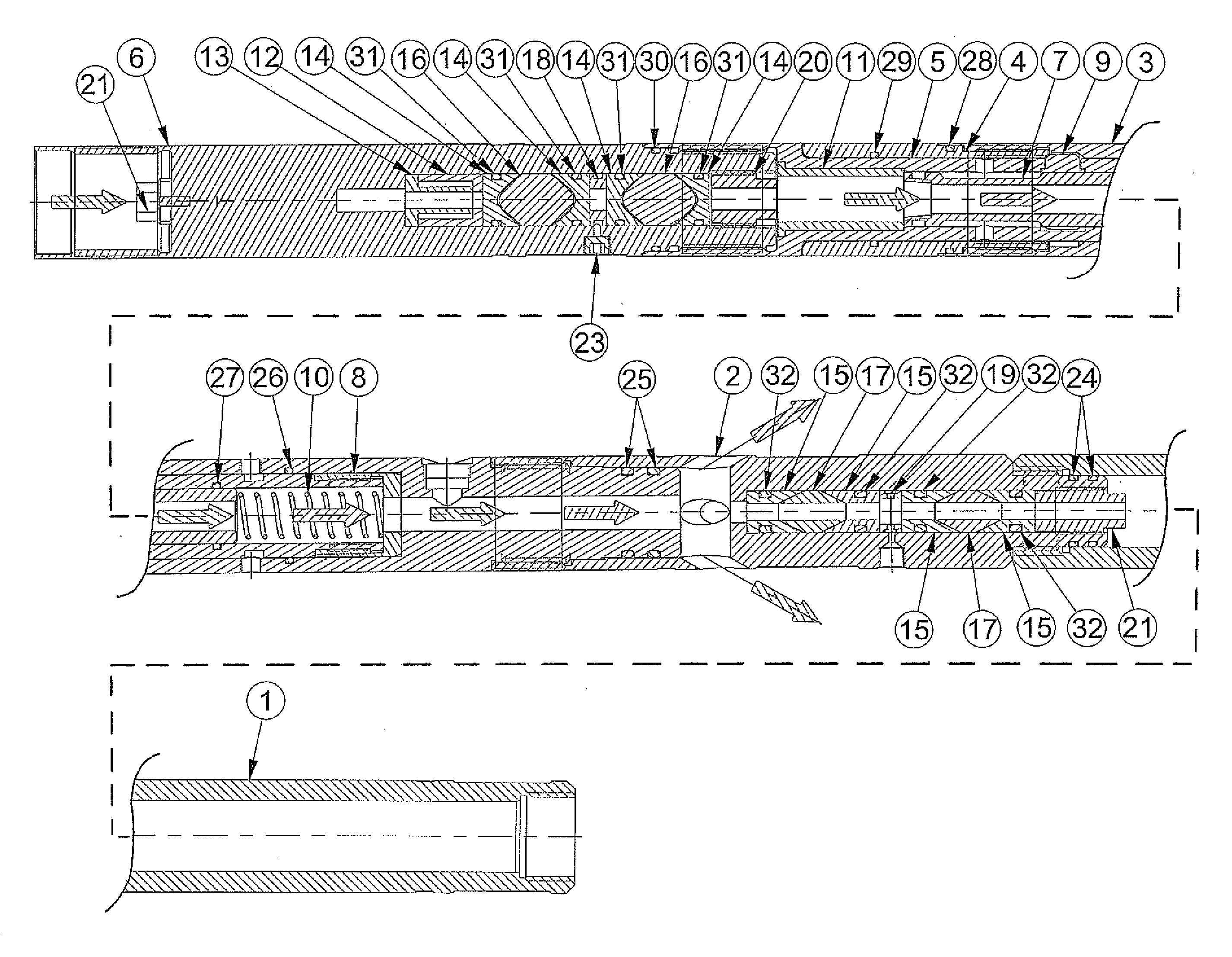
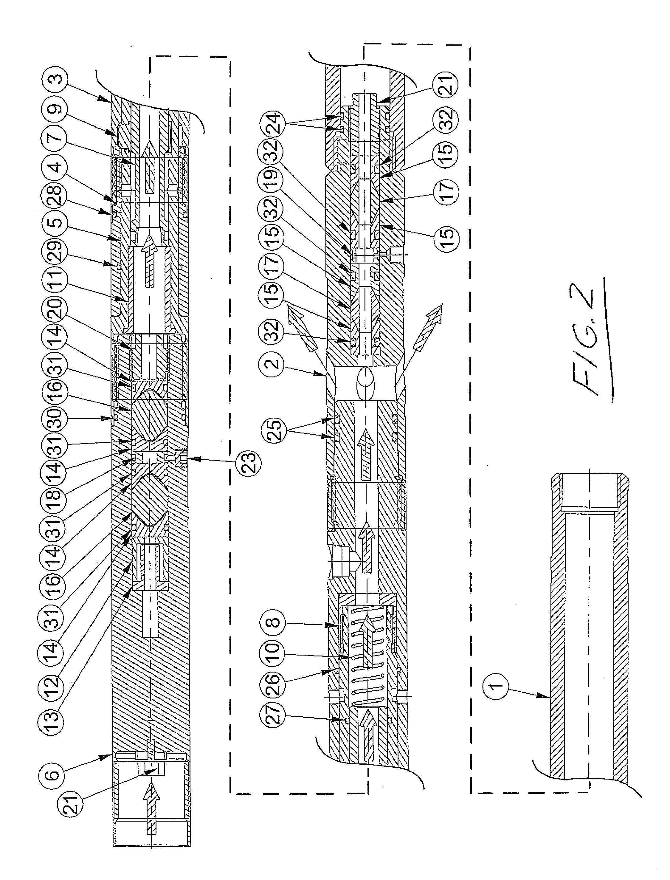
[0048]With reference to the drawings, the cable head features an outer housing with an actuating piston 7 slidably disposed therein. The housing features and upper housing and a lower housing, each of which are formed by a number of components.

[0049]Referring to FIG. 3, the upper housing features an upper pack-off sub 6 forming an upper end of the upper housing and a key-retaining housing 5 threadingly secured to a bottom end portion of the upper pack-off sub 6 with the interior spaces of these two parts open to one another and sealed together by an o-ring 30. The o-ring 30 annularly closes between the outer surface of the bottom end portion of the upper pack-off sub 30 and the inner surface of a cylindrical top end portion of the key-retaining housing 5 at a position above where the respective internal and external threads of the pack-off sub 6 and key-retaining housing 5 engage. The upper housing is completed by a key retainer cap 8 threaded onto a bottom end of the key-retaining ...


PUM


Abstract

A cable head for use with coiled tubing electric line in well operations has upper and lower housings attached by a shearable connection to allow release of the lower housing and any downhole equipment carried thereon. A piston is slidable within the housing by fluid pumped through the coil tooling to release a locking mechanism that otherwise prevents the shearing disconnect of the housings. Flow ports in the housing to allow pumping or circulation of fluid through the cable head are positioned to remain continuously open, regardless of the piston position, to maximize the range of flow rates over which fluid can be circulated. The electric line of coiled tubing is only stripped of its armor past sealed receipt thereof in a cable passage below the flow path of the fluid, thereby avoiding exposure of the conductor to the fluid to minimize the potential for damage or failure.

Description

FIELD OF THE INVENTION[0001]The present invention relates generally to cable heads for coiled tubing used in well operations, and more particular to such a cable head that facilitates hydraulic releasing of a downhole tool carried on the cable head, allows pumping of fluid downhole through the cable head over a wide range of flow rates and protects the cable from the fluid passing through the cable head.BACKGROUND OF THE INVENTION[0002]In well operations, downhole electrical equipment or tools are often deployed in the wellbore on the end of a length of coiled tubing, for example for logging of the well, use of downhole cameras or well perforation. The prior art has taught a number of cable heads that provide a releasable connection between the coiled tubing and the downhole electronic tool in case the tool should be become stuck in the wellbore and that also receive the end of the coiled tubing electric line where the line's conductor is stripped of its external armor in order to e...

Claims


Application Information

Patent Timeline
Patent Type & Authority Applications(United States)
IPC IPC(8): E21B19/22
CPCE21B17/023E21B17/206E21B17/06E21B17/028
Inventor SPENCE, DEAN
Owner SPENCE DEAN
Why Eureka
Try Eureka