Conveyor Belt Connector

a technology of conveying belt and connector, which is applied in the direction of belt fastening, belt/chain/gearing, transportation and packaging, etc., can solve the problems of transverse wire breaking and the risk of one or more wire hooks breaking, and achieve the effect of improving adhesion

Active Publication Date: 2012-01-26
MATO MASCH & METALLWARENFABRIK CURT MATTHAEI GMBH & CO KG
View PDF5 Cites 2 Cited by
  • Summary
  • Abstract
  • Description
  • Claims
  • Application Information

AI Technical Summary

Benefits of technology

[0012]The adhesive layer in the region of the individual shanks should bulge outwardly at least until it is greater than the radius or side thickness of the shank section. The further the bulge extends away from the substrate, the better the shanks of the wire hook are held in place.
[0013]In order to improve adhesion between the adhesive layer and the shanks of the wire hooks, in accordance with one advantageous refinement of the present invention, it is provided that the shanks of the wire hooks are coated or otherwise provided with an adhesive agent, especially a primer.

Problems solved by technology

Thus, especially when the belt is moved in a concave belt guide and / or must move through a plurality of deflection rollers, there is a risk that one or more of the wire hooks will break.
Also, in a connection in which a transverse wire is used to position the wire hooks relative to one another, there is a risk that the transverse wire will break, and broken ends of the wire hooks will project beyond the transport plane of the belt.

Method used


Image

  • Conveyor Belt Connector
  • Conveyor Belt Connector

Examples


Embodiment Construction

[0022]For purposes of description herein, the terms “upper”, “lower”, “right”, “left”, “rear”, “front”, “vertical”, “horizontal” and derivatives thereof shall relate to the invention as oriented in FIG. 1. However, it is to be understood that the invention may assume various alternative orientations and step sequences, except where expressly specified to the contrary. It is also to be understood that the specific devices and processes illustrated in the attached drawings, and described in the following specification, are simply exemplary embodiments of the inventive concepts defined in the appended claims. Hence, specific dimensions and other physical characteristics relating to the embodiments disclosed herein are not to be considered as limiting, unless the claims expressly state otherwise.

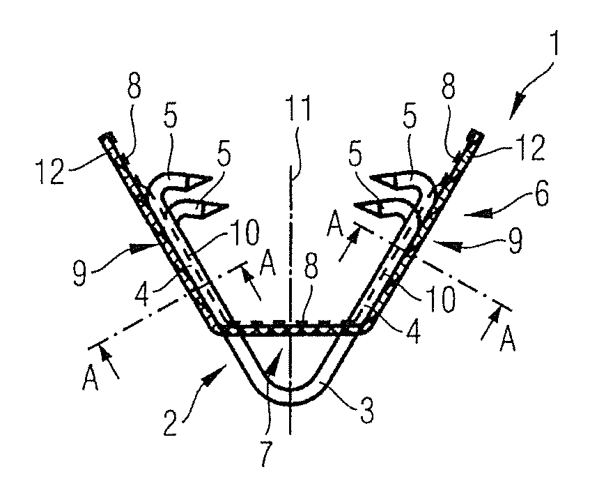
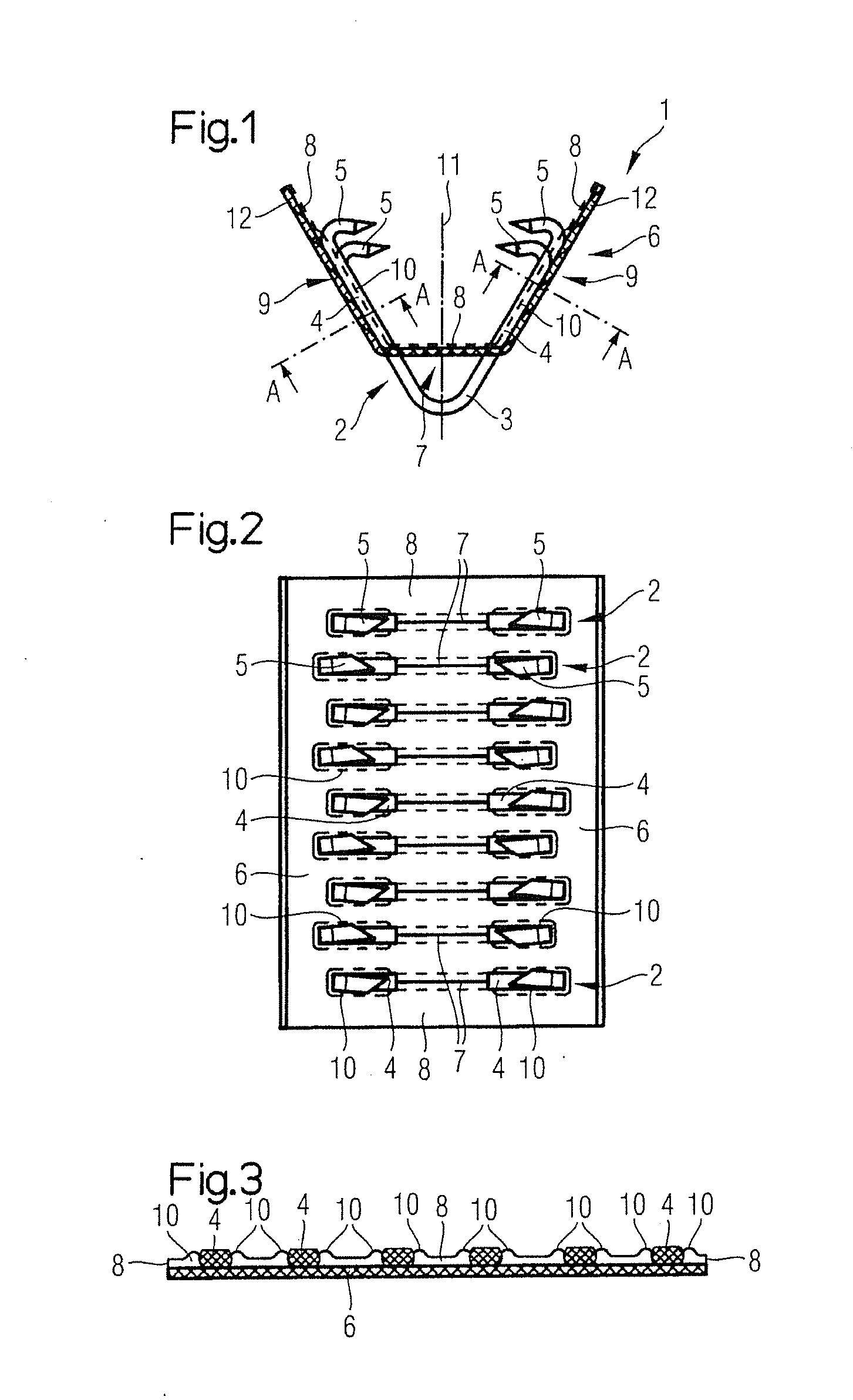
[0023]The connector element 1 depicted in the figures attaches to one end of a conveyor belt (not shown). Refer to the disclosure of EP 1 338 825 A1 in this regard.

[0024]The illustrated connecto...


PUM


Abstract

A conveyor belt connector has a plurality of wire hooks arranged in a pre-defined relationship. A strip shaped substrate has slots in which the loops of the wire hooks are received. The strip is shaped to completely cover the shanks of the wire hooks, and includes an adhesive layer on the interior side thereof in which the shanks of the wire hooks are imbedded prior to assembly on a conveyor belt to retain the same in their predefined relationship.

Description

CLAIM OF PRIORITY[0001]Applicants hereby claim the priority benefits under the provisions of 35 U.S.C. §119, basing said claim of priority on European Patent Application Serial No. 10007667.8, filed Jul. 23, 2010. In accordance with the provisions of 35 U.S.C. §119 and Rule 55(b), a certified copy of the above-listed European patent application will be filed before grant of a patent.BACKGROUND OF THE INVENTION[0002]The present invention relates to a connector element having individual wire hooks arranged adjacent to one another for attaching to one end of a conveyor belt. Each wire hook has a loop region, shanks that are connected to the loop region, and angled tips that are connected to the shanks. The connector element also has a strip-like substrate for holding the wire hooks. The substrate is provided with apertures arranged parallel to one another for receiving the wire hooks therein. The loop region of each wire hook is gripped in an associated one of the apertures. The connec...

Claims


Application Information

Patent Timeline
Patent Type & Authority Applications(United States)
IPC IPC(8): B65G15/30
CPCF16G3/00F16G3/04
Inventor HEROLD, WOLFGANG
Owner MATO MASCH & METALLWARENFABRIK CURT MATTHAEI GMBH & CO KG
Why Eureka
Try Eureka