LED lead frame and method of making the same

a lead frame and lead wire technology, applied in the field can solve the problems of high cost of led wire frame, and achieve the effect of facilitating robust interconnection and overall configuration

Inactive Publication Date: 2012-01-26
HON HAI PRECISION IND CO LTD
View PDF9 Cites 2 Cited by
  • Summary
  • Abstract
  • Description
  • Claims
  • Application Information

AI Technical Summary

Benefits of technology

[0007]An object of the present invention is to provide an LED lead frame in which the leads are interconnected by common bus lines so as to facilitating robust interconnection and overall configuration.

Problems solved by technology

However, the above fabricating method is complex and the wire and leads need be made from noble metal, so the conventional LED lead frame resulting cost high.

Method used


Image

  • LED lead frame and method of making the same
  • LED lead frame and method of making the same
  • LED lead frame and method of making the same

Examples


Embodiment Construction

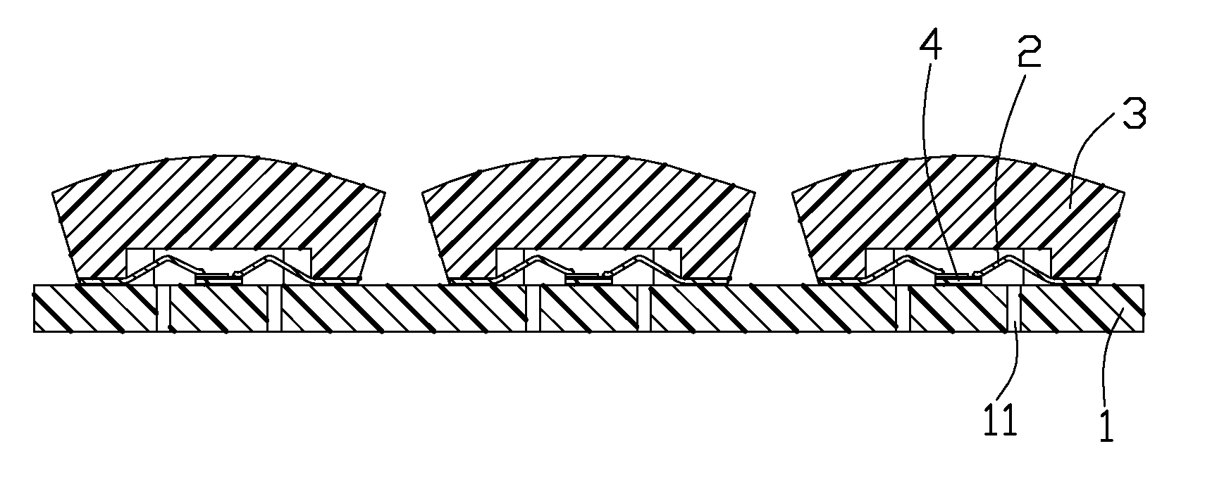
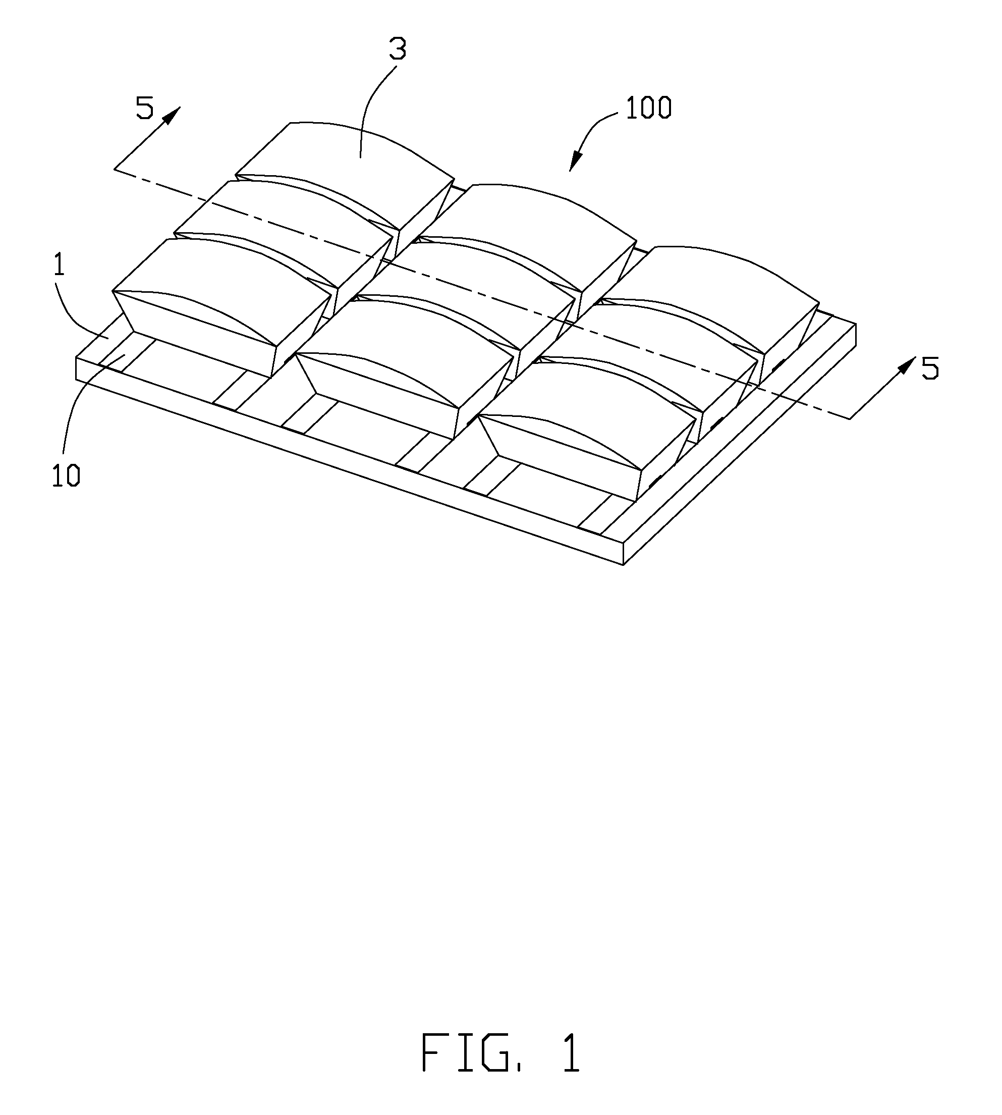
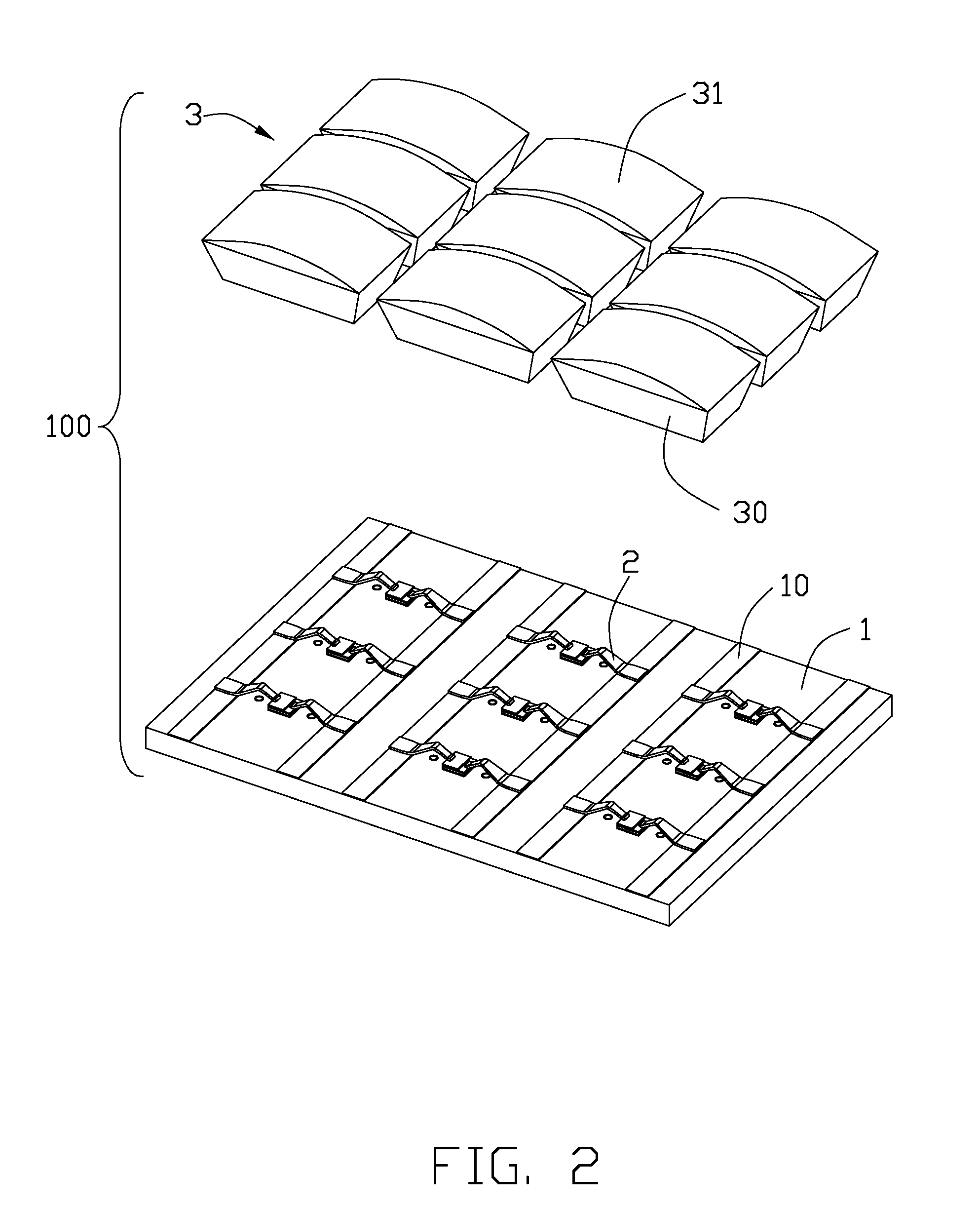
[0016]Referring to FIG. 1 to FIG. 3, an LED lead frame made in accordance with a preferable embodiment of the present invention is shown. The LED lead frame is used to connect an LED chip 4 and includes a planar wiring board 1 made of printed circuit board, a pair of contacts 2, and a cover 3 covered upon the board 1.

[0017]The top surface of the wiring board 1 is formed with a plurality of bus lines 10 by eroding. The bus lines 10 include a plurality of positive pole 110 and a plurality of negative pole 111, and the positive pole 110 and the negative pole 111 are arranged alternately on the top surface of the wiring board 1. The LED chip 4 is located between the positive pole 110 and the negative pole 111. Two through holes 11 are defined at opposite sides of the LED chip 4 on the wiring board 1.

[0018]The conductive leads 2 are formed by punching and soldered on the pole 10. Each conductive lead 2 includes a planar soldering portion 20, a bent portion 21 extending from the soldering...


PUM


Abstract

An LED lead frame assembly comprises a wiring board having a plurality set of positive and negative poles arranged on a top surface thereof A plurality of LED chips are disposed on the wiring board, and electrically bonded to the bus line. A transparent cover is arranged upon the wiring board and covering the LED chip and the conductive lead.

Description

BACKGROUND OF THE INVENTION[0001]1. Field of the invention[0002]The present invention relates to an LED lead frame and a method of making the same, and more particularly to an LED lead frame in which the leads are interconnected by common bus lines so as to facilitating robust interconnection and overall configuration.[0003]2. Description of Related Art[0004]A typical LED usually includes a lead frame with a housing of concave cavity in which a LED chip is seated. At least two conductive leads are mounted in the lead frame to be connected to the LED chip. The lead is partially embedded in the housing with one end thereof exposed in the cavity and the other end extending out of the housing for being mounted to an external device. The conductive lead is preferably plated with silver so as to obtain better light-reflection performance and better conductivity. The concave cavity is filled with transparent sealing polymer after the LED chip is securely bonded in the cavity of the housing...

Claims


Application Information

Patent Timeline
IPC IPC(8): H01L33/62H01L33/08H01L33/52
CPCF21K9/90F21Y2101/02F21Y2105/001H01L33/58H01L33/62H01L2224/48472H05K3/32H05K2201/0311H05K2201/09063H05K2201/10106H05K2201/1031H05K3/284F21Y2105/10F21Y2115/10Y02P70/50
Inventor CHENG, ANDREWCHENG, CHIH-PI
Owner HON HAI PRECISION IND CO LTD
Why Eureka
Try Eureka