

Stator for electric rotating machine
a technology for rotating machines and stator coils, which is applied in the direction of dynamo-electric components, dynamo-electric machines, windings insulation materials, etc., can solve the problems of lowering the insulation properties of stator coils, affecting the normal operation of electric rotating machines, and adjacent pairs of bridging wires so as to prevent adjacent pairs of bridging wires from colliding or sliding against each other, and effectively suppress the displacement of bridging wir
- Summary
- Abstract
- Description
- Claims
- Application Information
AI Technical Summary
Benefits of technology
Problems solved by technology
Method used
Image


Examples
first embodiment
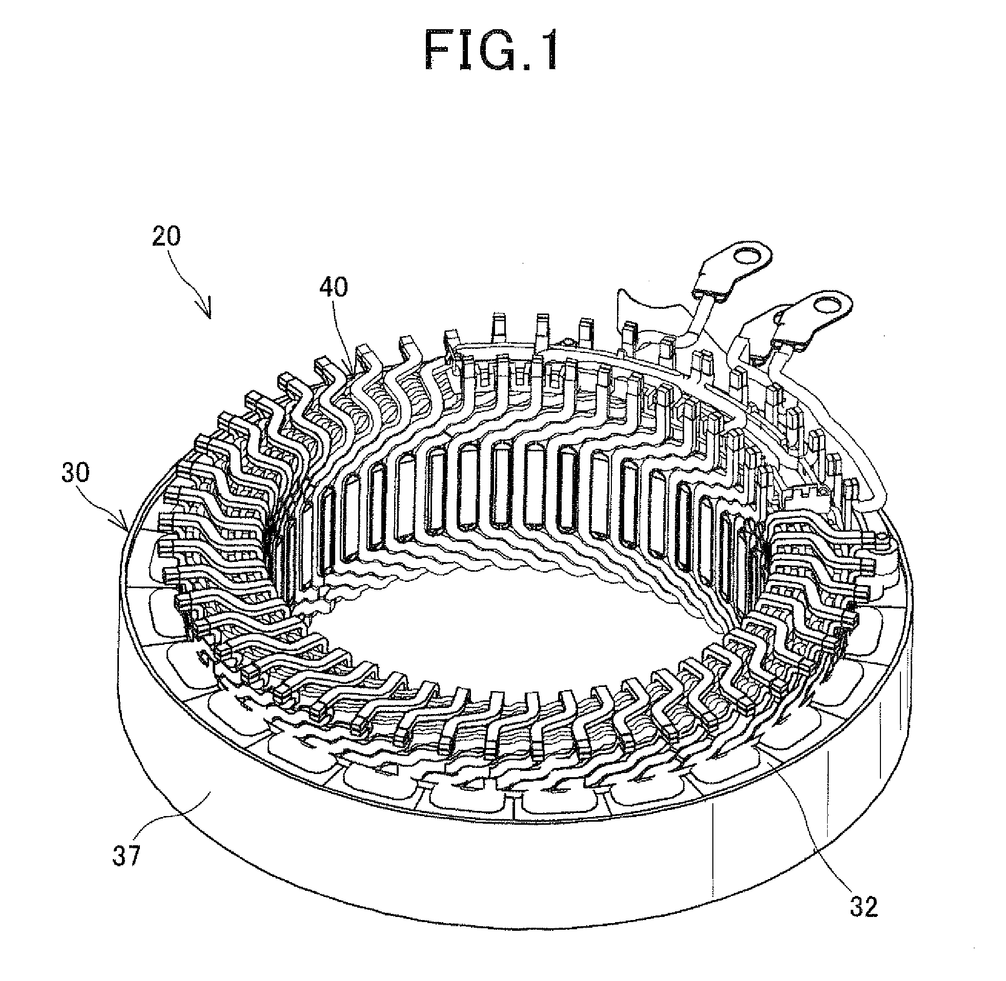
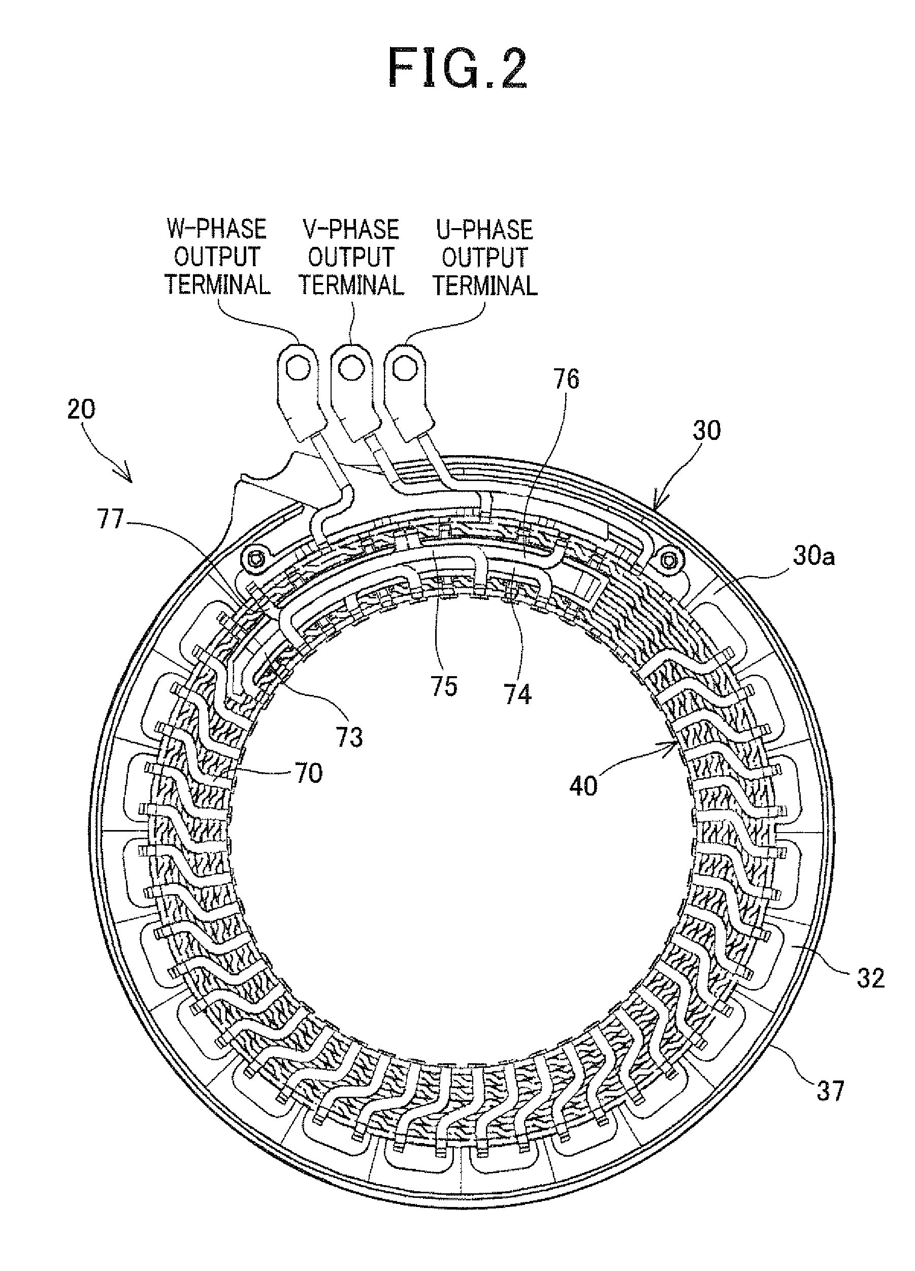
[0058]FIGS. 1-3 together show the overall configuration of a stator 20 according to a first embodiment of the invention. The stator 20 is designed for use in, for example, an electric rotating machine which is configured to function both as an electric motor and as an electric generator in a motor vehicle. The electric rotating machine further includes a rotor (not shown) that is rotatably disposed so as to be surrounded by the stator 20. The rotor includes a plurality of permanent magnets that form a plurality of magnetic poles on a radially outer periphery of the rotor to face a radially inner periphery of the stator. The polarities of the magnetic poles alternate between north and south in the circumferential direction of the rotor. In addition, in the present embodiment, the number of the magnetic poles formed in the rotor is equal to eight (i.e., four north poles and four south poles).
[0059]As shown in FIGS. 1-3, the stator 20 includes an annular stator core 30 and a three-phas...
second embodiment
[0162]In this embodiment, the first to the fifth bridging wires 73-77 are fixed to one another by pressure-joining (i.e., pressing and thereby joining together) the overlapping parts of the bridging wires 73-77.
[0163]Specifically, as shown in FIG. 21A, the first to the fifth bridging wires 73-77 according to the present embodiment are respectively identical to those according to the first embodiment. Moreover, the relative arrangement of the first to the fifth bridging wires 73-77 according to the present embodiment is the same as that according to the first embodiment.
[0164]Accordingly, in the present embodiment, for each of the first to the fifth bridging wires 73-77, the main portion of the bridging wire partially overlaps at least one of the main portions of the other bridging wires either in the axial direction or in the radial direction of the stator core 30. Moreover, each pair of the overlapping parts of the main portions of the first to the fifth bridging wires 73-77 are pr...
third embodiment
[0173]In this embodiment, the stator 20 includes a connector 85 as shown in FIG. 25. The connector 85 is made by insert-molding first to fifth bridging wires 73A-77A in a resin 86. That is, the first to the fifth bridging wires 73A-77A are fixed to one another in the resin 86.
[0174]Specifically, as shown in FIG. 26A, the first to the fifth bridging wires 73A-77A are almost respectively identical to the first to the fifth bridging wires 73-77 according to the first embodiment. Moreover, the relative arrangement of the first to the fifth bridging wires 73A-77A is the same as that of the first to the fifth bridging wires 73-77. However, unlike in the first embodiment, the fourth and fifth bridging wires 76A and 77A are joined together to form a common end portion D′ thereof.
[0175]Moreover, as shown in FIGS. 25 and 26B, the connector 85 has, as a whole, an arc shape conformed to the annular shape of the coil end part 42a of the stator coil 40. The first to the fifth bridging wires are i...
PUM
 Abstract
Description
Claims
Application Information