Stereoscopic 3D Images and Video on a Non-Stereoscopic 3D Capable Screen

a technology of stereoscopic 3d and capable screens, which is applied in the direction of pictoral communication, color television details, electrical appliances, etc., can solve the problems of not being able to meet the requirements of stereoscopic 3d image and video input, the merits of stereoscopic 3d may not outweigh the cost savings of maintaining a conventional non-stereoscopic 3d capable screen, and the vast majority of screens in use today. achieve the effect of increasing the lifecycle of screens

Inactive Publication Date: 2012-01-26
GEFEN
View PDF5 Cites 20 Cited by
  • Summary
  • Abstract
  • Description
  • Claims
  • Application Information

AI Technical Summary

Benefits of technology

[0006]The present invention overcomes these drawbacks of the prior art and provides a device, system and method of outputting and synchronizing stereoscopic 3D images and videos onto a screen for accurate, stereoscopic 3D viewing by a user. The present invention may function as a stand-alone device or be incorporated into other devices. Therefore, older or less technologically advanced screens may be adapted to properly display stereoscopic 3D images without having native stereoscopic 3D screen support, thereby increasing the lifecycle of a screen and saving consumers from the cost of a full upgrade. The present invention is not limited to non-stereoscopic 3D capable screens and may be applied to any screen.

Problems solved by technology

In particular, a stereoscopic 3D capable screen is necessary to properly display a stereoscopic 3D video source because a stereoscopic 3D video source outputted form a non-stereoscopic 3D capable screen is unwatchable.
However, the vast majority of screens in use today, are not compatible with stereoscopic 3D image and video input sources.
Although consumers and businesses may desire to adopt stereoscopic 3D technology, purchasing and replacing a non-stereoscopic 3D screen with a stereoscopic 3D capable screen may be cost prohibitive.
For some consumers, the merits of stereoscopic 3D simply may not outweigh the cost savings of maintaining a conventional non-stereoscopic 3D capable screen.

Method used


Image

  • Stereoscopic 3D Images and Video on a Non-Stereoscopic 3D Capable Screen
  • Stereoscopic 3D Images and Video on a Non-Stereoscopic 3D Capable Screen
  • Stereoscopic 3D Images and Video on a Non-Stereoscopic 3D Capable Screen

Examples


Embodiment Construction

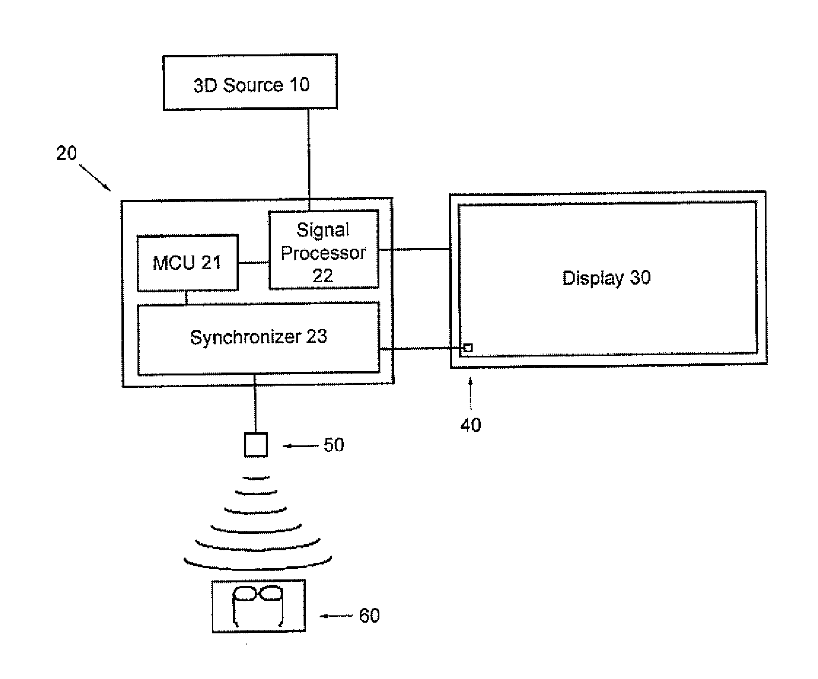
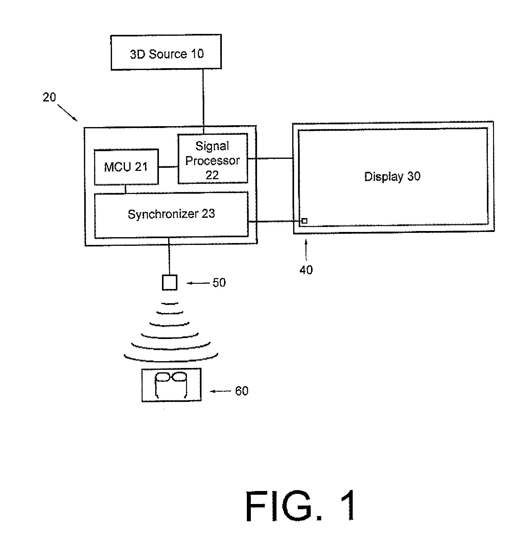
[0016]One embodiment of the present invention is illustrated in the block diagram of FIG. 1. Converter 20 is connected to screen 30 and receives a stereoscopic 3D image outputted from stereoscopic 3D image source 10. stereoscopic 3D image source 10 may be any source capable of providing stereoscopic 3D images, such as for example, a recordable media player, a set top box, a LAN, video game console or the like. Converter 20 includes an input port for receiving a stereoscopic 3D image signal and an output port for transmitting the modified stereoscopic 3D signal to screen 30. In an alternative embodiment, stereoscopic 3D image source 10 is incorporated into converter 20. The operation of converter 20 is discussed in greater detail below. Screen 30 may be of any size and can be a Projector, CRT, LCD, OLED, PDP or any other type of screen. While the present invention is most useful for a screen incapable of correctly displaying a stereoscopic 3D image, the invention may be applied to st...


PUM


Abstract

A method of providing a stereoscopic 3D image or video on a non-stereoscopic 3D screen. This includes receiving an alternating frame sequence of left and right images where a marker is embedded into the left or the right image. The alternating sequential frame with the embedded marker is output to the non-stereoscopic 3D screen. The markers outputted from the non-stereoscopic 3D screen are detected by an optical sensor. A synchronization signal is sent via a communication channel to an eye control device to synchronize the eye control device with the non-stereoscopic 3D screen, based on the detected markers displayed on the screen.

Description

BACKGROUND OF THE INVENTION[0001]1. Field of the Invention[0002]This invention relates to viewing stereoscopic 3D images and video on non-stereoscopic 3D capable screens.[0003]2. Description of Related Art[0004]Stereoscopic 3D screen technology has recently increased in popularity with consumers and allows a viewer to perceive images in stereoscopic 3D. A plethora of methodologies and standards exist for displaying stereoscopic 3D images and video. Many of these techniques are proprietary and all require specialized equipment and screens. In particular, a stereoscopic 3D capable screen is necessary to properly display a stereoscopic 3D video source because a stereoscopic 3D video source outputted form a non-stereoscopic 3D capable screen is unwatchable. However, the vast majority of screens in use today, are not compatible with stereoscopic 3D image and video input sources.[0005]Although consumers and businesses may desire to adopt stereoscopic 3D technology, purchasing and replacin...

Claims


Application Information

Patent Timeline
Patent Type & Authority Applications(United States)
IPC IPC(8): H04N13/04
CPCH04N13/0497H04N13/0429H04N13/332H04N13/398
Inventor GEFEN, HAGAINIVALA, TEEMUCRUZ, JOSEPH
Owner GEFEN
Why Eureka
Try Eureka