Light boxes with uniform light distribution

a technology of light distribution and light boxes, applied in the field of systems, methods and apparatus for mounting, displaying, and/or lighting panels, can solve the problems of difficulty in reading words, blotchy and unappealing panel display, and limitations of each light sour

Inactive Publication Date: 2012-01-26
3FORM +1
View PDF3 Cites 60 Cited by
  • Summary
  • Abstract
  • Description
  • Claims
  • Application Information

AI Technical Summary

Benefits of technology

[0013]Implementations of the present invention provide light boxes that evenly distribute light throughout the light box. In particular, implementations of the present invention include light boxes of various sizes and configurations that provide uniform light distribution and illumination across the light box panels.

Problems solved by technology

While each type of light sources provides differing advantages, each light source also has limitations and drawbacks when used in a conventional light box application.
Thus, the resulting panel display appears blotchy and unappealing.
Moreover, if words are displayed on the panel, then the words may become difficult to read due to the hot and cold spots produced by the light source.
Scalloping generally causes the panel to appear striped, which is typically unappealing and lowers the aesthetic appearance of the light box.
Although hot spots, cold spots, and scalloping may occur at almost any location on a panel, a general problem location may be around the corners and edges of the light box.
The edges and corners of conventional light boxes may receive poor light distribution due to position of the light source within the box, as well as the geometry of the light box itself.
For example, providing an even light distribution throughout the light box may be difficult due to light box size restrictions put in place by the Americans with Disabilities Act (ADA).
Light boxes satisfying the low-profile requirement of the ADA, often do not allow for the uniform diffusion of light necessary for even light distribution throughout the light box, and particularly the edges and corners of the light box.
Accordingly, there are a number of disadvantages in conventional light boxes that can be addressed.

Method used


Image

  • Light boxes with uniform light distribution
  • Light boxes with uniform light distribution
  • Light boxes with uniform light distribution

Examples


Embodiment Construction

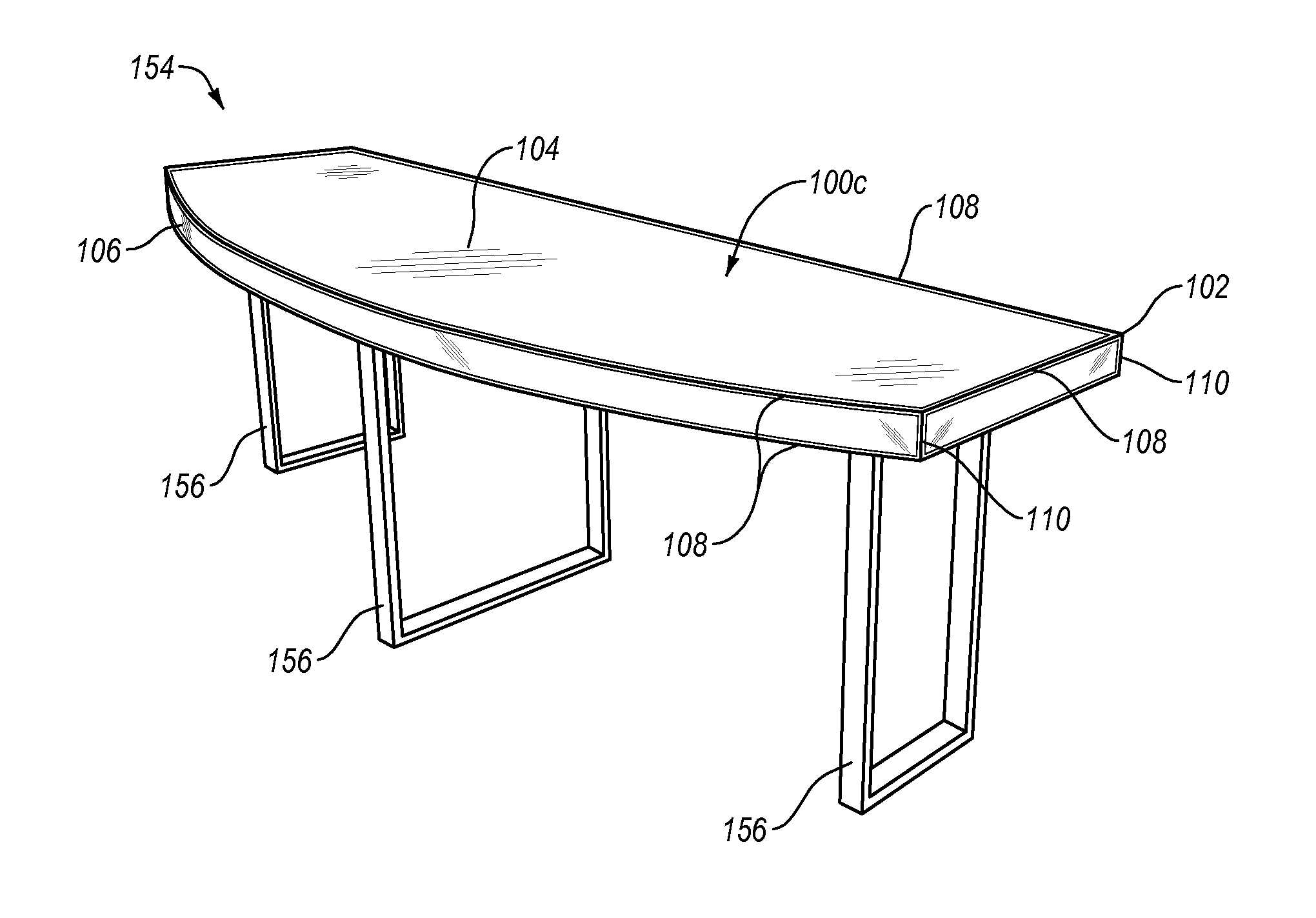
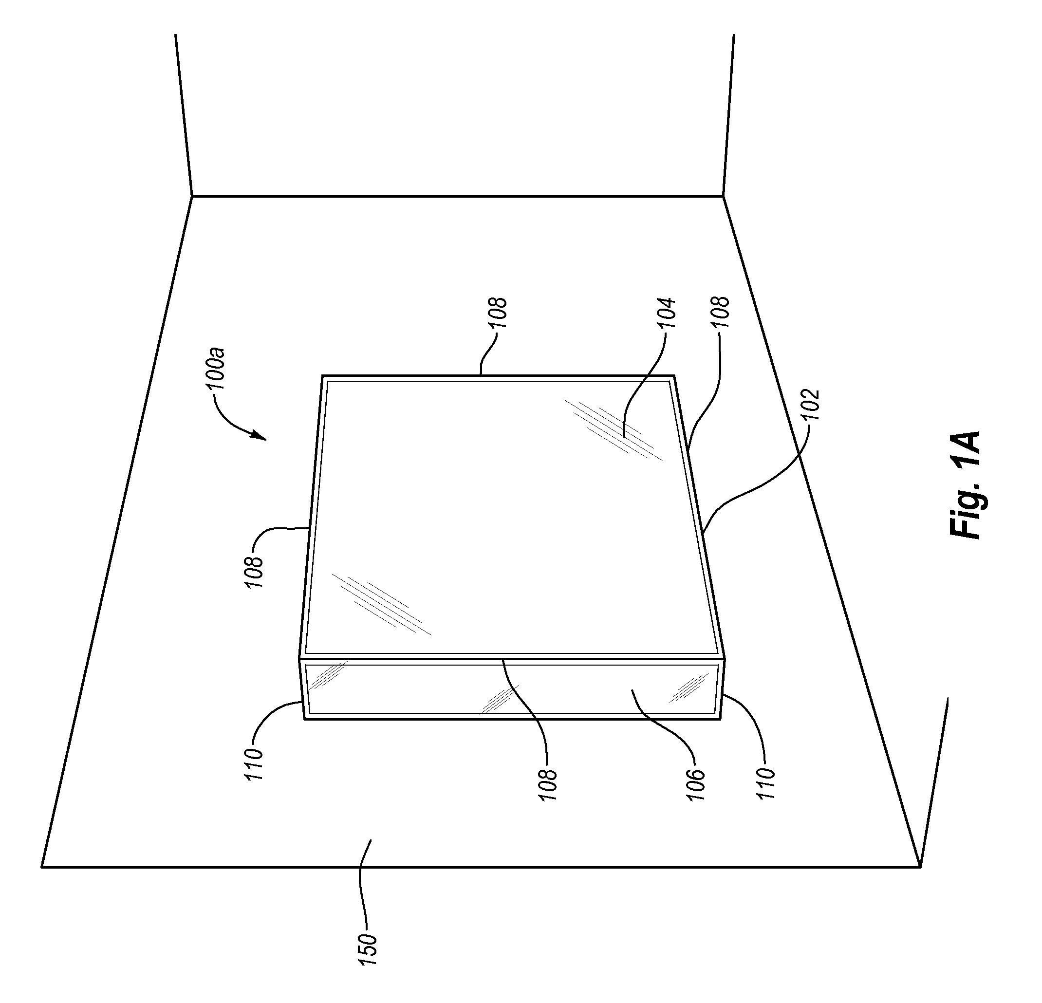
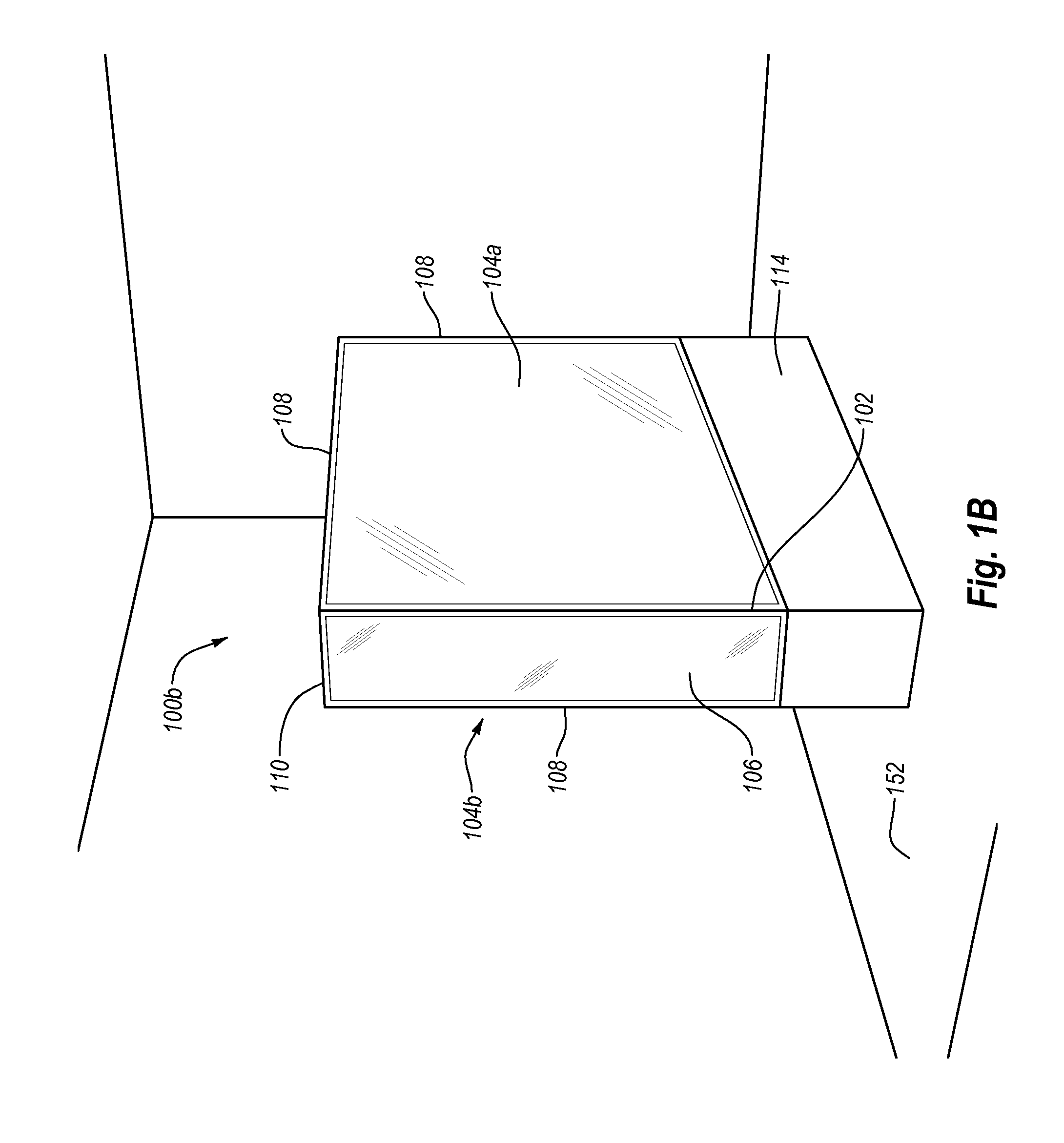
[0031]Implementations of the present invention provide light boxes that evenly distribute light throughout the light box. In particular, implementations of the present invention include light boxes of various sizes and configurations that provide uniform light distribution and illumination across the light box panels.

[0032]For example, implementations of the present invention provide light boxes with uniquely configured light sources that are positioned, arranged, and directed within the light box to provide uniform light distribution on the light box panels. For instance, one implementation of the present invention includes light boxes with a light source positioned and arranged to provide a uniform light distribution over the entire visible portion of the light box panel(s). For example, implementations of the present invention position LED fixtures proximate one or more edges of the light box and aim or direct the LEDs within the light box such that the light emitted from the ind...


PUM


Abstract

Light boxes for uniformly illuminating panels include a frame that supports one or more translucent panels. The light boxes further include a light source positioned within the light box. Example light sources can include fluorescent bulbs, incandescent lights, and/or light-emitting-diodes. In at least one implementation, a manufacturer positions a relatively limited number of light sources aimed and/or positioned in a particular way to uniformly distribute light throughout the light box and evenly across the translucent panels such that there are no shadows, hot spots or other non-uniform light patterns on the translucent panels.

Description

CROSS-REFERENCE TO RELATED APPLICATIONS[0001]The present application is a 371 U.S. National Stage of PCT Application No. PCT / US2010 / 029086, filed Mar. 29, 2010 entitled “LIGHT BOXES WITH UNIFORM LIGHT DISTRIBUTION,” which claims the benefit of priority to the U.S. Provisional Application No. 61 / 164,617, filed Mar. 30, 2009, entitled “Reconfigurable LED Light Boxes;” and U.S. Provisional Application No. 61 / 263,322, filed Nov. 20, 2009, entitled “Light Boxes with Uniform Light Distribution;” U.S. Design application 29 / 355,551 filed Feb. 9, 2010, entitled “Light Box Wrap.” The present application is also a continuation-in-part application of U.S. Design application 29 / 355,552 filed Feb. 9, 2010, entitled “Desk Front Light Box.” The entire content of the above-mentioned patent applications are incorporated in their entirety herein by reference.BACKGROUND OF THE INVENTION[0002]1. The Field of the Invention[0003]This invention relates to systems, methods, and apparatus for mounting, displ...

Claims


Application Information

Patent Timeline
Patent Type & Authority Applications(United States)
IPC IPC(8): F21V13/02F21V33/00
CPCA47B13/12F21Y2105/001F21Y2101/02G02B6/0011G02B6/0096G09F13/04G09F13/18G09F2013/0422G09F2013/1804G09F2013/1831G09F2013/1854G09F2013/222F21S8/033F21S8/04F21V33/0012F21Y2105/10F21Y2115/10G09F13/0422
Inventor FISHER, KEVIN L.RAISSEN, MARK HOWARDHERNANDEZ, ESTEBAN D.MARTIN, GUILLAUMEDAMEN, MICHAELHILLSTROM, BRIAN
Owner 3FORM
Why Eureka
Try Eureka