Wind power plant

a wind power plant and wind turbine technology, applied in the direction of machines/engines, mechanical equipment, rotary machine parts, etc., can solve the problems of limiting the damping that can be achieved in this way, affecting alternating loads have a much more detrimental effect on the life of teeth and other components, so as to achieve optimal protection against damage, the effect of longest possible service life and low friction loss

Active Publication Date: 2012-01-26
IMO HOLDING GMBH
View PDF8 Cites 24 Cited by
  • Summary
  • Abstract
  • Description
  • Claims
  • Application Information

AI Technical Summary

Benefits of technology

The invention is a wind power plant with a unique mounting system for the rotor shaft. The system includes three connecting elements, with one of them being rotatable. This allows for easy mounting on a stationary frame of the wind power plant. The rotor shaft is always in a vibration node, even when there are vibrations in the system. The freewheel is protected from damage by vibrations, which increases its lifespan. The invention also includes a bearing with low friction losses, which prevents the hub shaft from vibrating in the radial direction. The load-bearing capacity of the bearing is maximized because the contacts between the rolling bodies and their raceways are linear contacts, reducing surface pressure.

Problems solved by technology

The technical problem addressed by this patent is how to improve the damping capacity of a wind power system without causing excessive wear and tear on its components.

Method used


Image

  • Wind power plant
  • Wind power plant
  • Wind power plant

Examples


Embodiment Construction

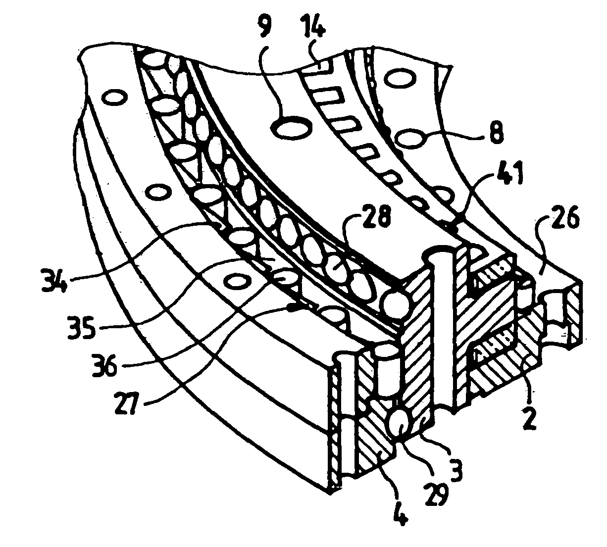
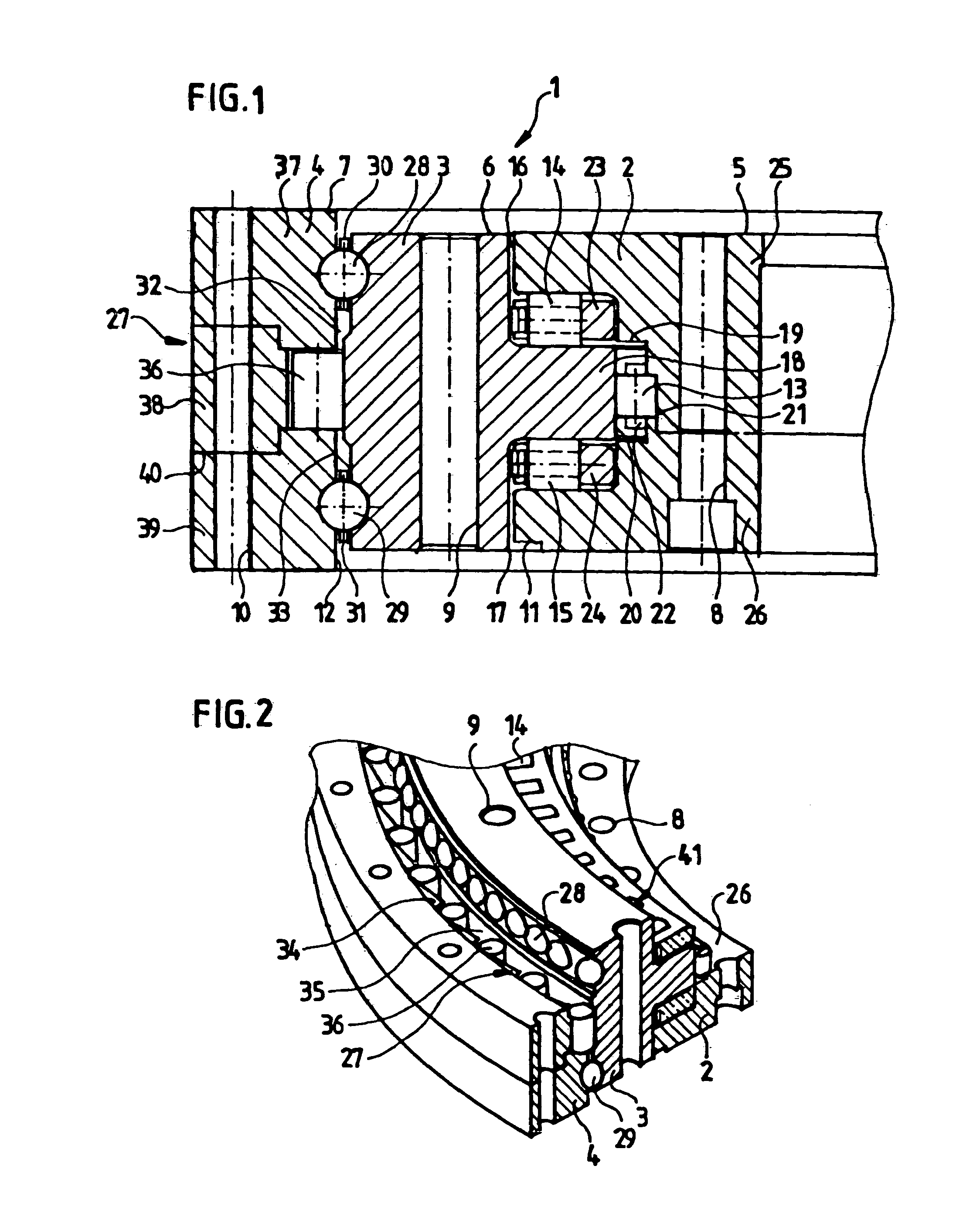
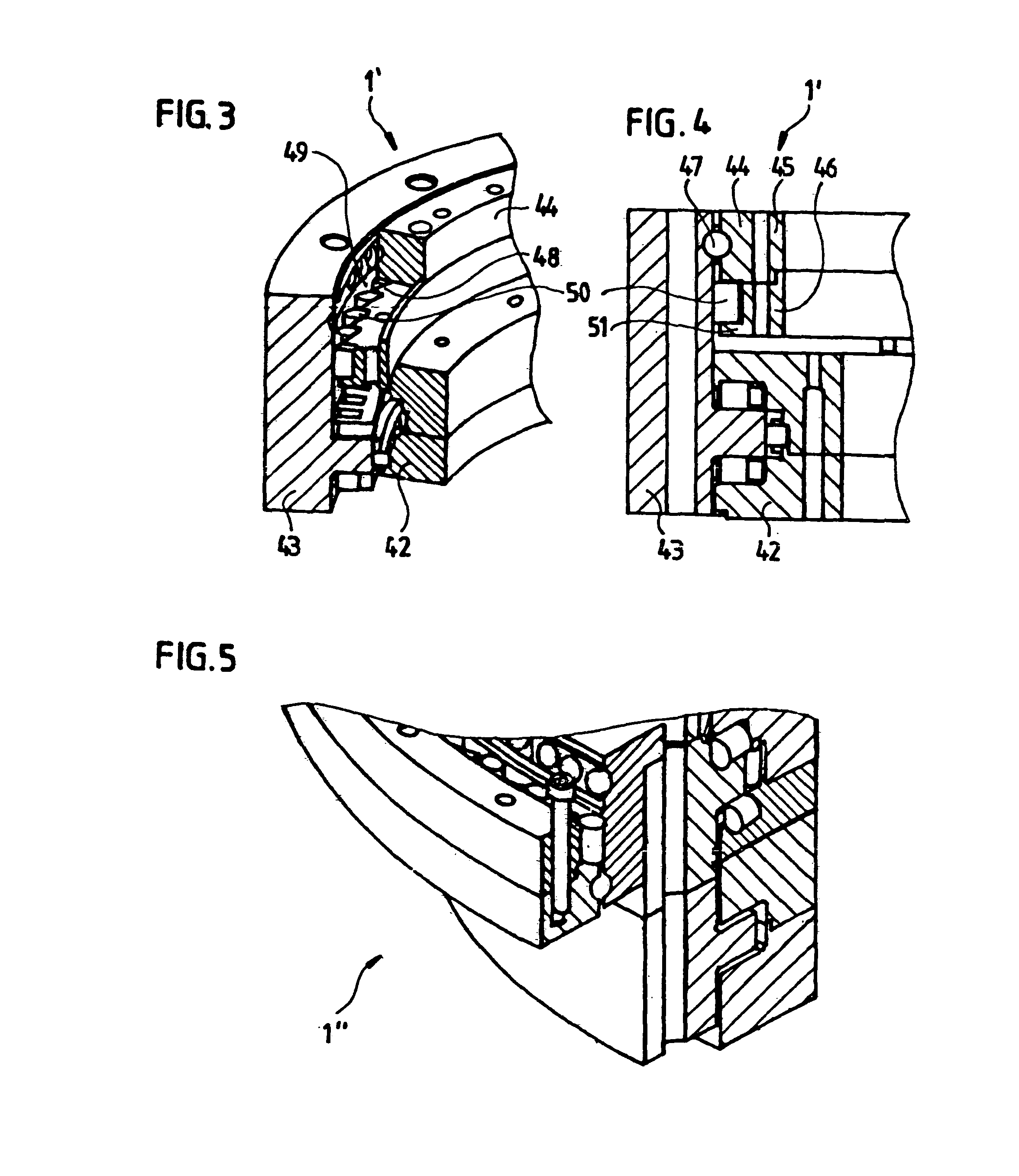
[0045]FIG. 1 shows, as an example of the invention, a cross section through the rings of a rolling bearing 1 for the rotor of a wind power plant, whose wind wheel has an axis of rotation pointing approximately in the direction of the wind. The rolling bearing 1 can be used as the main bearing of the wind power plant, i.e., the bearing that also carries the rotor hub; particularly in the case of a gearless wind power plant. The bearing 1 can also serve as an additional bearing that guides the rotor shaft, or it is connected to a connector, particularly the output, of a gearbox or a coupling in the transmission chain from the wind wheel to the generator.

[0046]The bearing 1 includes three rings 2, 3, 4 that are rotatable relative to one another. In the example of FIG. 1, the inner ring 2 is affixed to the frame of the nacelle, the middle ring 3 is connected to the rotor hub or rotor shaft or to the output of a gearbox or coupling, and the outer ring 4 is connected to the rotor of the g...


PUM


Abstract

The invention is directed to a wind power plant having a rotor mounted rotatably about an axis directed approximately in the wind direction, and having at least two mutually concentric annular elements for connection to oppositely rotatable system components of the wind power plant, one of which comprises means for connection to the rotor of the wind power plant or to a drive shaft of a gearbox coupled thereto; at least one element having a freewheel characteristic is disposed between the two connection elements and together with them forms a freewheel, at least one connection element being provided with at least one integrated raceway for a row of rolling bodies rolling thereon.

Description


Claims


Application Information

Patent Timeline
Owner IMO HOLDING GMBH
Why Eureka
Try Eureka