Vertebral fixing system

a technology of fixing system and vertebrae, which is applied in the field of vertebral fixing system, can solve the problems of difficulty in using such hooks, paralysis of patients, and small pedicles, and achieves the effects of improving the stability of the patien

Active Publication Date: 2012-01-26
ZIMMER SPINE SAS
View PDF3 Cites 48 Cited by
  • Summary
  • Abstract
  • Description
  • Claims
  • Application Information

AI Technical Summary

Benefits of technology

[0028]When the locking means are in their second position, this ensures effective clamping of the two ligature strands, thereby preventing them from moving.

Problems solved by technology

Nevertheless, it is difficult to use such hooks since the operator must under no circumstances interfere with the spinal cord that extends along the center of the vertebral canal, since otherwise there is a danger of paralyzing the patient.
Nevertheless, they are necessarily introduced into the pedicles of the vertebrae, and under certain circumstances such pedicles can be small in size or damaged.

Method used


Image

  • Vertebral fixing system
  • Vertebral fixing system
  • Vertebral fixing system

Examples


second embodiment

[0052]FIGS. 4 to 7B show the fixing system.

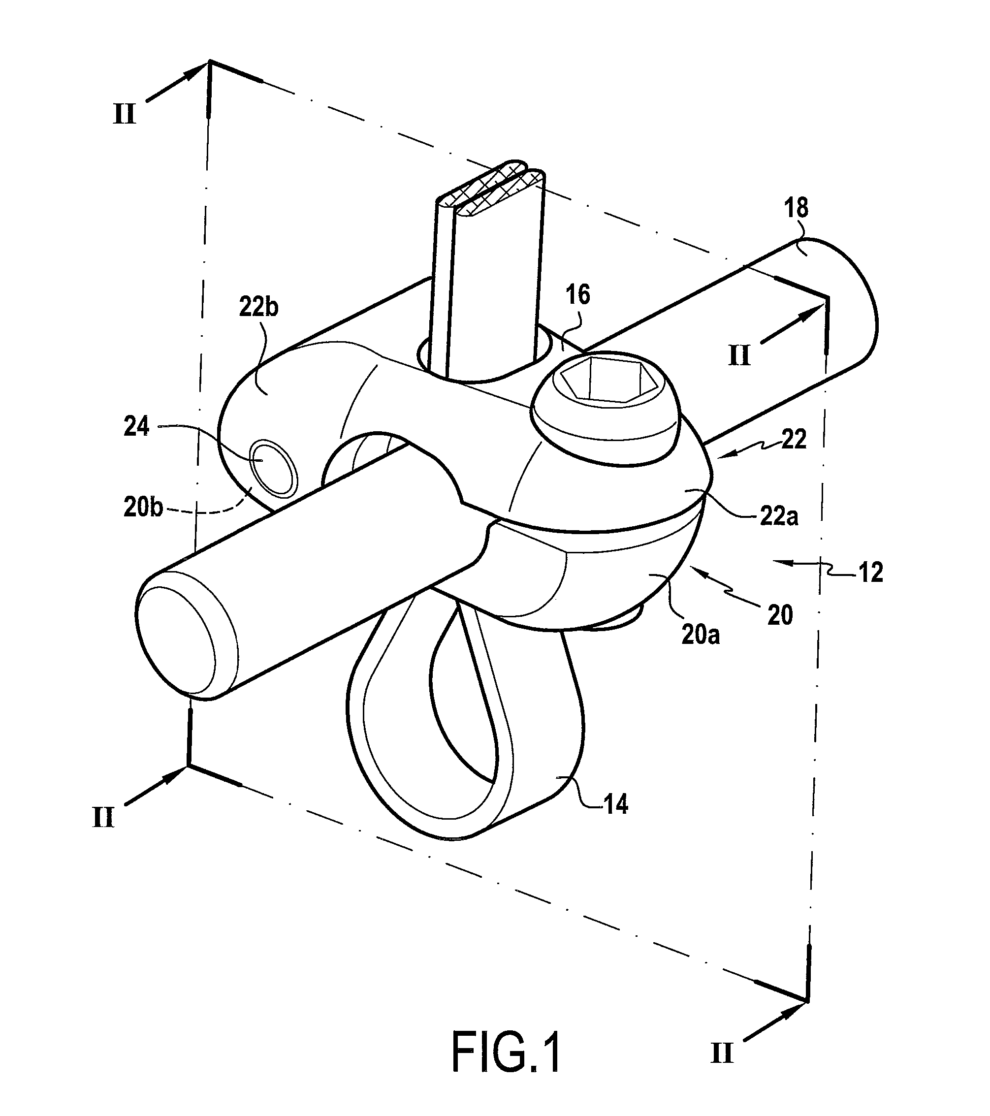
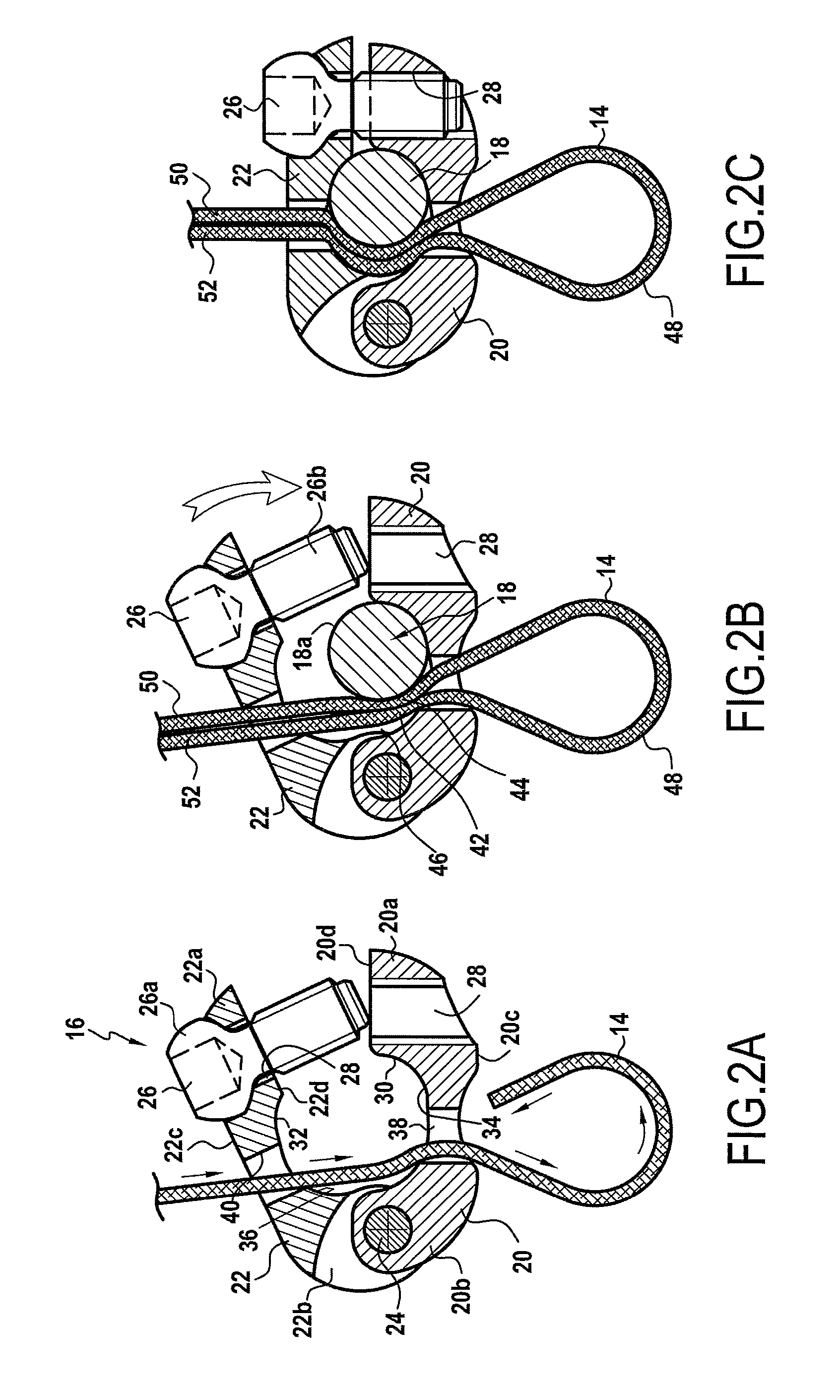
[0053]In these figures, there can be seen the rod 18, the connecting part now referenced 12′, and the flexible ligature 14.

[0054]In this embodiment, the connecting part 12′ is constituted by a part 50 that is generally U-shaped. The inside wall of this part is constituted by a bottom 52 of substantially semicylindrical shape and by two substantially plane portions 54 and 56 that correspond to the two limbs of the part 50. The width l of the recess 58 formed in the part 50 is substantially equal to the diameter d of the rod 18. On its outside face 50a which is circularly symmetrical about a longitudinal axis of the part 50, there is provided a thread 60 occupying its upper portion. The thread 60 is located entirely above the rod 18 when it is put into place in the recess 58. The thread 60 is designed to co-operate with a clamping ring 62 that constitutes the adjustable locking means. This ring has a slightly frustoconical bore 64 with an ins...

first embodiment

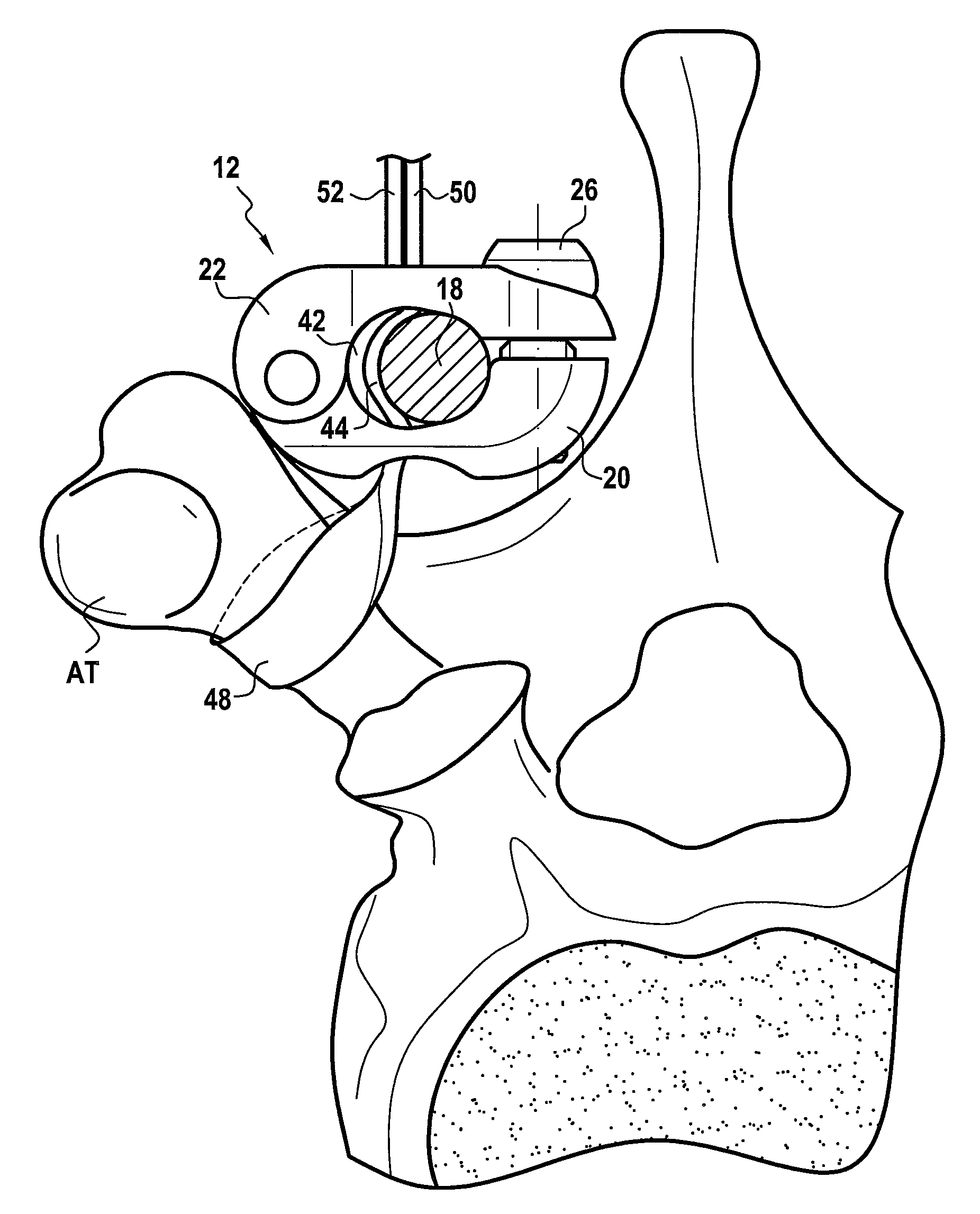
[0058]In the configuration shown in FIG. 7B, the middle strands 42 and 44 of the flexible ligature 14 are disposed respectively one in each of the passageways 76 and 78, i.e. on either side of the rod 18. This configuration likewise presents all of the advantages described with reference to the device since the free ends 50 and 52 of the ligature 14 are accessible for exerting the desired traction in order to obtain suitable clamping on the spinous process prior to locking the clamping ring 62 on the part 52.

[0059]This second embodiment presents the advantage of being simpler in design since it serves in particular to avoid making two longitudinal parts constituting a kind of clamp hinged on the pin 24.

[0060]It will be understood that in both embodiments, the locking means are constituted by an element that is distinct from the connecting part and that is removable therefrom. In addition, in both cases, the locking means co-operate with the connecting part by screw engagement. It is...


PUM


Abstract

A vertebral fixing system comprising a connecting part with two longitudinal elements coupled to each other at a first end and having mutually facing recesses for receiving a rod. A portion of a flexible ligature extends through orifices of the two longitudinal elements to define a loop opposite two free ends of the flexible ligature. The two longitudinal elements are engaged at a second end of the connecting part via a locking means. When the two longitudinal elements of the connecting part are locked at the second end of the connecting part, two strands of the flexible ligature are pinched between the rod and a wall of the mutually facing recesses of the two longitudinal elements of the connecting part, preventing the flexible ligature from moving in translation relative to the connecting part.

Description

CROSS-REFERENCE TO RELATED APPLICATIONS[0001]This application is a continuation of U.S. patent application Ser. No. 12 / 375,265, entitled “VERTEBRAL FIXING SYSTEM,” filed Mar. 9, 2009, which claims foreign priority benefits under 35 U.S.C. §119 to International Application No. PCT / FR2006 / 050898, filed Sep. 18, 2006, which claims priority to French Application Nos. FR 0650609, filed Feb. 22, 2006, and FR 0509570, filed Sep. 29, 2005. All applications listed herein are incorporated by reference in their entireties.TECHNICAL FIELD OF THE INVENTION[0002]The present invention relates to vertebral fixing system suitable for being mounted on a vertebra.[0003]An intended field of application is particularly, but not exclusively, the treatment of scoliosis, or more generally correcting abnormal curvatures of the spine.BACKGROUND OF THE RELATED ART[0004]The spine is constituted by superposed vertebrae that are normally in alignment along a vertical axis, going from the lumbar vertebrae to the ...

Claims


Application Information

Patent Timeline
Patent Type & Authority Applications(United States)
IPC IPC(8): A61B17/70A61B17/88
CPCA61B17/7032A61B17/707A61B17/7053A61B17/7041
Inventor BACCELLI, CHRISTIANBELLIARD, KARL P.MAZDA, KEYVAN
Owner ZIMMER SPINE SAS
Why Eureka
Try Eureka