Traction Control System in a Vehicle, Vehicle Including Traction Control System, and Traction Control Method

a technology of traction control system and traction control method, which is applied in the direction of braking system, process and machine control, instruments, etc., can solve the problems of delay in starting traction control and control termination, and achieve the effect of easy termination, reduced difference, and increased driving power

Active Publication Date: 2012-01-26
KAWASAKI MOTORS LTD
View PDF10 Cites 21 Cited by
  • Summary
  • Abstract
  • Description
  • Claims
  • Application Information

AI Technical Summary

Benefits of technology

[0015]In accordance with this configuration, the control termination condition in a case where the vehicle is driving in a road surface condition in which the drive wheel is less likely to slip changes easily according to the vehicle state. The traction control can be terminated easily when the vehicle is driving in such a road surface condition. Thus, according to a road surface condition difference, it can be determined properly whether or not to terminate the traction control.
[0016]The controller may increase the driving power gradu...

Problems solved by technology

If the control start condition is insensitive to the change in the vehicle state, it cannot be detected correctly that the vehicle has entered the road of the bad road surface condition, and starting of the traction control might be delayed.
If the cont...

Method used


Image

  • Traction Control System in a Vehicle, Vehicle Including Traction Control System, and Traction Control Method
  • Traction Control System in a Vehicle, Vehicle Including Traction Control System, and Traction Control Method
  • Traction Control System in a Vehicle, Vehicle Including Traction Control System, and Traction Control Method

Examples


embodiment 1

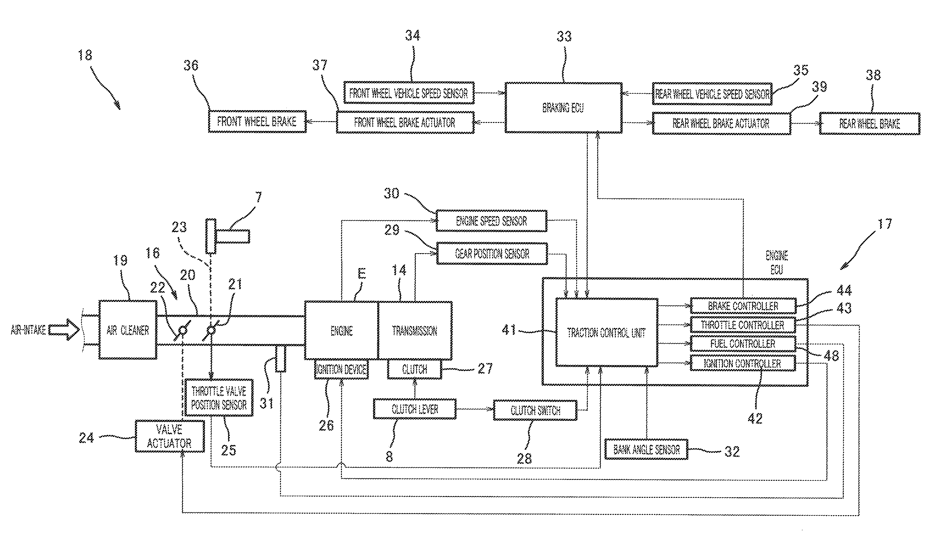
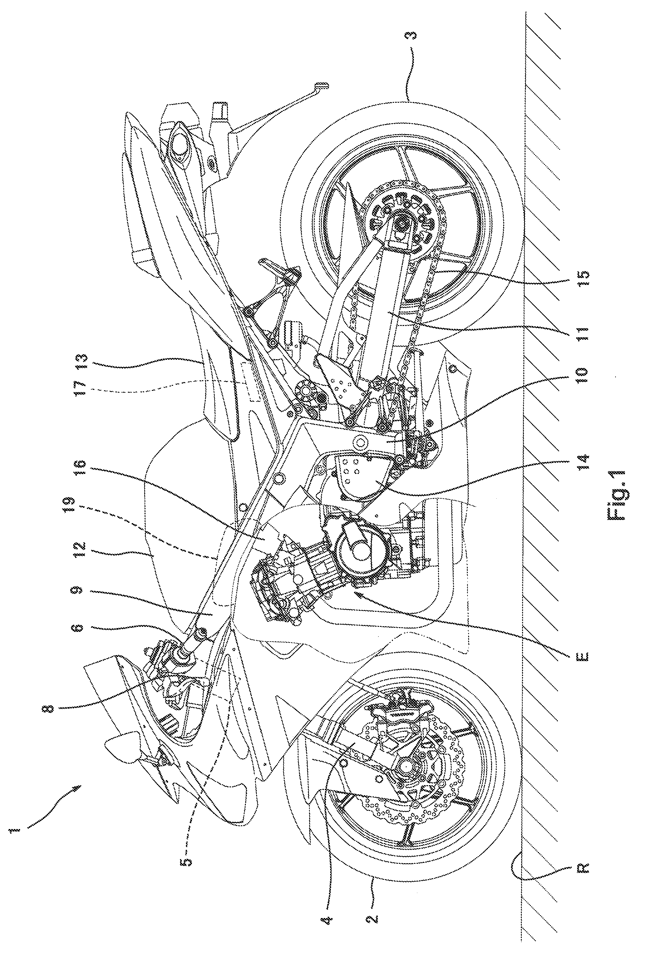
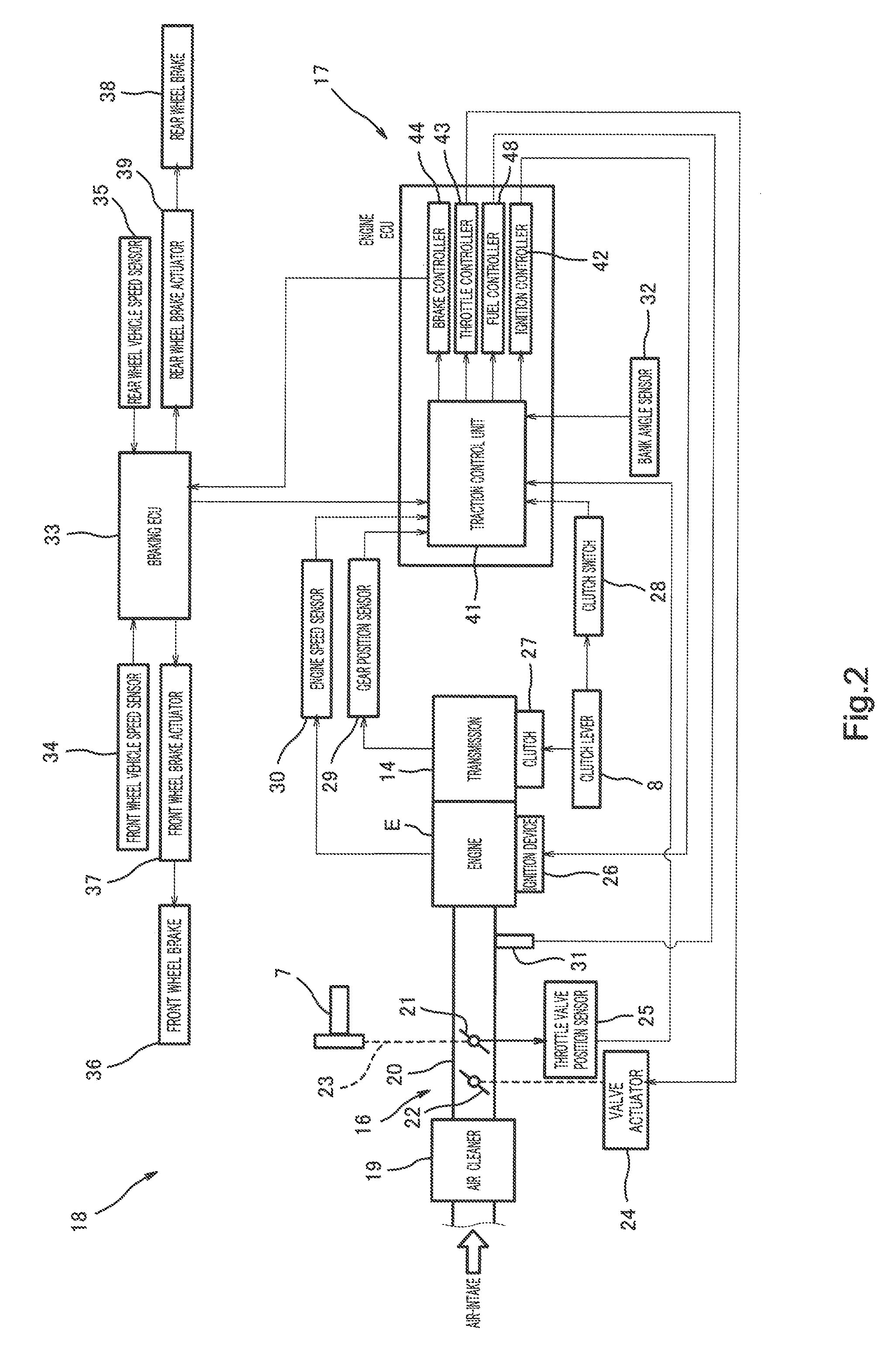
[0038]FIG. 1 is a left side view of the motorcycle 1 including the traction control system 18 of the present invention. As shown in FIG. 1, the motorcycle 1 includes a front wheel 2 which is a driven wheel and a rear wheel 3 which is a drive wheel. The front wheel 2 is rotatably mounted to a lower end portion of a front fork 4 extending substantially vertically. The front fork 4 is mounted to a steering shaft (not shown) via an upper bracket provided at an upper end portion thereof and an under bracket (not shown) provided below the upper bracket. The steering shaft is rotatably supported by a head pipe 5. A bar-type steering handle 6 extending rightward and leftward is attached to the upper bracket.

[0039]A throttle grip 7 (see FIG. 2) of the handle 6 is gripped by the driver's right hand and rotated by the right hand to operate a throttle device 16 as described later. The throttle grip 7 is a throttle input device. A clutch lever 8 is provided in front of a grip of the handle 6 wh...

embodiment 2

[0087]FIG. 8 is a graph showing exemplary changes in the first control start threshold MS1, the second control start threshold MS2, the first control termination threshold ME1 and the second control termination threshold ME2, which occur with time, of the present invention. As shown in FIG. 8, the second control start threshold MS2 set for the road surface condition in which the rear wheel 3 is more likely to slip is set smaller than the first control start threshold MS1 in the same vehicle state and set to change sensitively to a change in the vehicle state. The second control termination threshold ME2 set for the road surface condition in which the rear wheel 3 is more likely to slip is set smaller than the first control termination threshold ME1 in the same vehicle state and set to change insensitively to a change in the vehicle state.

[0088]When the motorcycle 1 is driving on the slippery road surface, the vehicle state changes more greatly than when the motorcycle 1 is driving ...


PUM


Abstract

A traction control system in vehicle comprises a detector for detecting a monitored value which changes according to a degree of a drive wheel slip; a condition determiner for determining whether or not the monitored value meets a control start condition and whether or not the monitored value meets a control termination condition; and a controller for executing traction control to reduce a driving power of the drive wheel during a period of time from when the condition determiner determines that the monitored value meets the control start condition until the condition determiner determines that the monitored value meets the control termination condition; the condition determiner being configured to set at least the control start condition variably based on a slip determination factor which changes according to a vehicle state and such that the control start condition changes more greatly according to the vehicle state than the control termination condition.

Description

BACKGROUND OF THE INVENTION[0001]1. Field of the Invention[0002]The present invention relates to a traction control system built into a vehicle such as a motorcycle.[0003]2. Description of the Related Art Japanese Laid-Open Patent Application Publication No. Hei. 7-103009 discloses a conventional traction control system in a vehicle. The conventional traction control system is configured to monitor a value indicating the degree to which a drive wheel slips. The degree to which the drive wheel slips tends to be high when a vehicle is driving on a road surface (hereinafter also referred to as a bad road surface) such as a rough road surface, or a slippery road surface which is wet due to rain or the like and has a low friction coefficient. It is expected that the monitored value increases as the degree to which the drive wheel slips increases. The traction control system determines whether or not the monitored value exceeds a threshold. When it is determined that the monitored value e...

Claims


Application Information

Patent Timeline
IPC IPC(8): B60T8/175G06F19/00
CPCB60T8/175B60T8/1706
Inventor MATSUDA, YOSHIMOTO
Owner KAWASAKI MOTORS LTD
Why Eureka
Try Eureka